UML Notations and Symbols
1. What Are UML Notations
UML is a standardized modeling language that is used for visualizing different types of systems. It was originally developed for software systems. However, it is now adopted for many other systems as well. It employs standard UML notations for visualizing, specifying, and documenting different components of a system.
It is a non-programming language whose sole purpose is to document all parts of the system without going deep into the implementation and programming details. Since all stakeholders in a system have different perspectives, UML has several types of diagrams to represent various aspects of the same system. The depth of details, philosophy, and purpose of each UML diagram is different.
2. UML Notations and Symbols Explained
UML is composed of entities, relationships, and diagrams that are represented by specific UML notations and symbols. Appropriate and intelligent use of all these components results in effective, understandable, and correct models. The main building blocks of a UML model are discussed below.
2.1 Structural Things
A structural thing describes the nouns of the system, i.e., the static or physical part of a model. The main types of structural things are class, object, interface, collaboration, use case, component, and node.
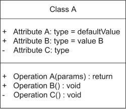
Class Notation
A class represents the structure and functions of an object. A class can also be abstract, which means its functionalities are not defined.
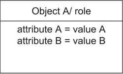
Object Notation
An object describes an entity, i.e., a building block of the system. Objects decompose large systems into small, manageable, and understandable modules. Objects are instances of classes, i.e., they contain all class parameters in the real world. So, we can say, class is a virtual concept, and its concrete form is an object.
Class and object have the same UML symbol, but the object name is underlined to differentiate between class and object.
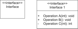
Interface Notation
An interface is a template that defines different functions without implementation details represented by a circle notation. A class that implements the interface also implements the functionality.
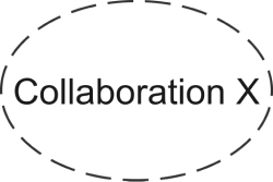
Collaboration Notation
A collaboration UML notation shows the relationship between two objects. It indicates that messages can pass between the objects. A dotted ellipse represents it.
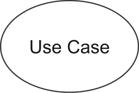
Use case Notation
A use case represents a goal completed by the system on access by the user. In simple words, the use case is the function triggered by the actor, i.e., the user. An actor can also be another part of the system or an individual.
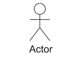
Actor Notation
An actor is any internal or external entity interacting with the system.
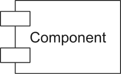
Component Notation
A component notation represents a part of the system.
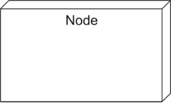
Node Notation
A node describes the physical part of the system. Examples are network, server, routers, etc.
2.2 Behavioral Things
Behavioral things are the UML symbols that represent behaviors or functions of the system. I.e., The verbs of the systems are behavioral things, i.e., interactions, activities, and state machines. The various types of behavioral things in UML notations are discussed below.
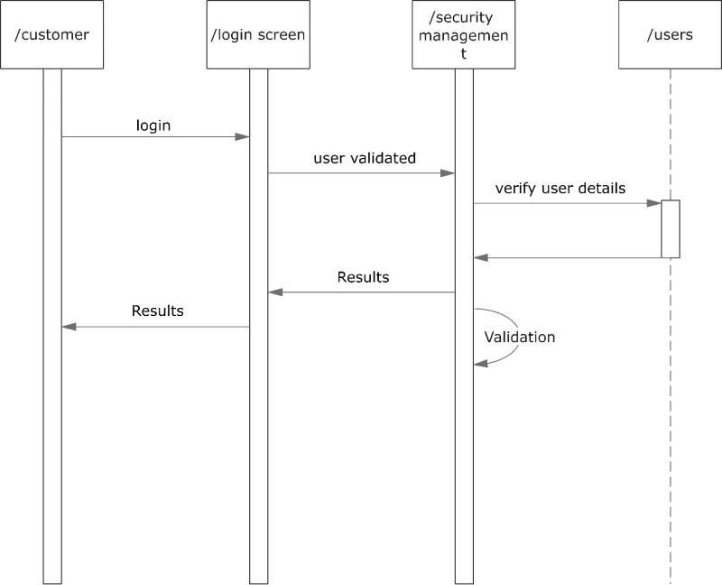
Interaction Notation
Interaction represents message exchange between two UML components. Interactions can be of two types;
Sequential used in the sequence diagram
Source: EdrawMax Community
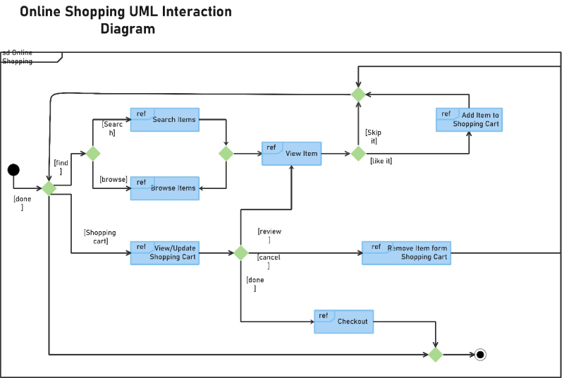
Collaborative used in a collaboration diagram
Source: EdrawMax Community
State Machine Notation
State machine captures different states of a system component. In other words, state machines show the lifecycle of a component. States include active, idle, or any other condition depending on the situation.
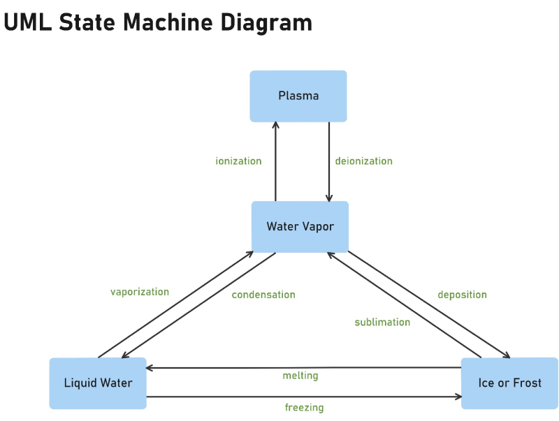
Source: EdrawMax Community
2.3 Grouping Things
When a system expands, keeping track of all components can be difficult and can cause major confusion. Therefore, UML notation includes grouping notation that helps organize the system. The grouping element in UML is package notation.
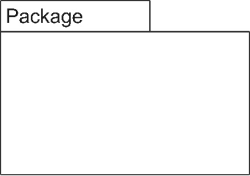
Package Notation
Package notation wraps the semantically related modeling elements of the system into one single cohesive unit.
2.4 Annotational Things
Annotational things explain different elements and their functionalities and helps in capturing vital supporting information. Annotational things include note UML notation.
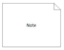
Note Notation
A note notation is added to a diagram to explain extra details about it.
2.5 Relationships
The relationship shows how two or more components of a UML system relate to each other with meaningful connections. It shows the association and how it describes the functionality of the model. Different types of relationships are shown below.
Source: EdrawMax Online
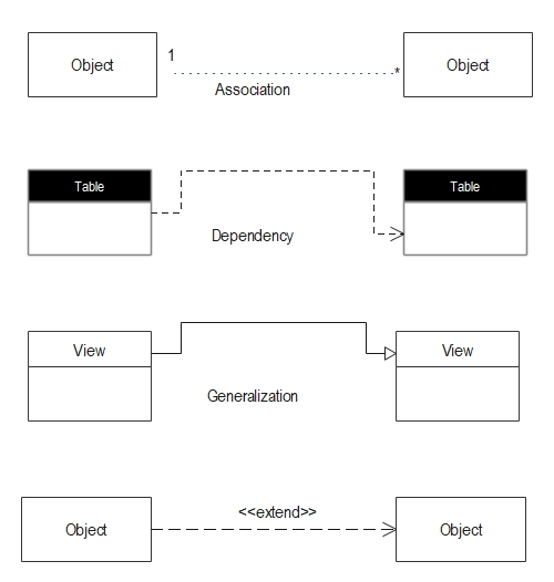
Dependency Notation
In the dependency relationship, one component depends on the target component, and the target changes affect the source. A dependency UML symbol is denoted by a dotted line with the arrow showing the direction of dependency.
Association Notation
Association relationship shows how many components are taking part in an interaction. The UML notation for association notation is a dotted line with arrows on both ends or no arrows. The multiplicity is shown at the ends of the line.
Generalization Notation
Generalization notation shows the relationship between a general entity and a specific entity. In other words, it offers a parent-child relationship. The UML symbol for generalization notation is a straight line with a hollow arrowhead on one end.
Extensibility Notation
Extensibility notation helps in enhancing the power of language. It includes additional elements to show extra aspects or behaviors of the system. The mechanisms to provide extensibility features are as follows.
- Stereotypes are used to represent new elements.
- Tagged values represent new attributes.
- Constraints represent the boundaries
3. Tips for Using UML Symbols
UML diagrams are like blueprints of a software system. The accuracy and efficiency of a system depend on the correct use of proper UML notations. If the UML diagram is drawn properly, it can be implemented in the required solution.
Object Management Group (OMG) manages the UML symbols and notations as OMG adopted UML as a standard in 1997. ISO also revises the UML edition periodically to cover the latest revisions.
3.1 Use a Professional UML Diagram Tool
EdrawMax UML symbols library is an exhaustive collection of notations and supports the latest UML versions. Find UML notations and symbols quickly from From EdrawMax Online>Symbol Library> UML Modelling. 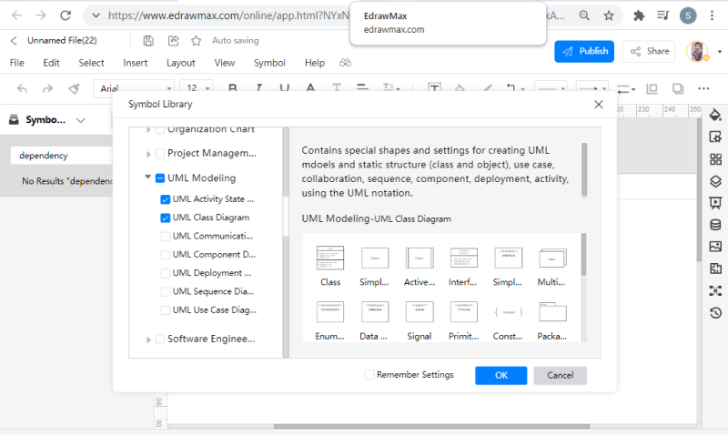
3.2 Create Symbols by Yourself
EdrawMax Online has a comprehensive UML symbols library, but some practitioners also want to use hand-drawn or specific symbols related to their particular system. In that case, you can also import your symbols and drawings in SVG, VSSX, and other formats. Go to the library option on the sidebar and click on the import icon. A new pop-up window will appear that you can use to import images, symbols, or data. 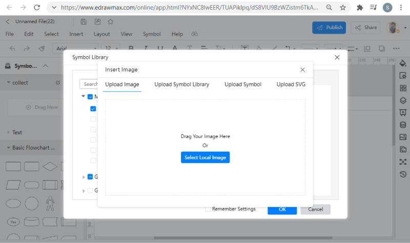
You can also learn more from this video. YouTube.
4. Conclusion
The Unified Modeling Language(UML) provides a standard way to design a software system. It helps in visualizing the overall structure and functionality of the system, even for the non-technical stakeholders. UML diagrams are based on standard UML notations recognized by ISO. EdrawMax Online is a powerful UML diagram tool with an exhaustive library for UML symbols and also for other 280+ diagram types. You can also use the free and fully customizable professional UML examples es available in the template community. Many general scenarios are already available in the templates community so that you can start fast on a firm foundation.