Free Editable UML Diagram Examples
The unified modeling language is a general-purpose language that illustrates the standard design of any system in software engineering. We use UML diagrams to visualize a project or a system to plan its activities and goals, and you can also use it to plan system designs in other fields. Read till the end to learn more about the UML diagram from its examples down here.
1. What Is UML Diagram
Visual representation makes it easier to understand the general idea behind any system or design. UML diagram uses the same approach towards modeling system design using pictures instead of plain text. UML diagrams illustrate software solutions, systems structures, and business processes. You can learn about which format of UML is suitable for you from our UML diagram examples. UML makes it easy to design any system in a standard way, and you can use it in various fields like business process modeling other than software engineering
2. The UML Diagram Examples
UML diagrams are commonly used to model software system designs and illustrate workflows, and business process flows. There are various UML diagrams based on the type of system you are modeling and your field of work. From our UML diagram examples down here, you will learn about various formats of a UML. It is mainly used to depict fundamental aspects of a system. There are many types of systems and designs; that is why UML diagrams come with a variety of features and layouts.
|
|
|
| UML Class Diagram Example | UML Sequence Diagram Example | UML Use Case Diagram Example |

|
|
|
| Java UML Diagram Example | UML State Diagram Example | UML Component Diagram Example |
|
|
|
| UML Deployment Diagram Example | UML Package Diagram Example | Basic UML Diagram Example |
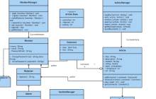
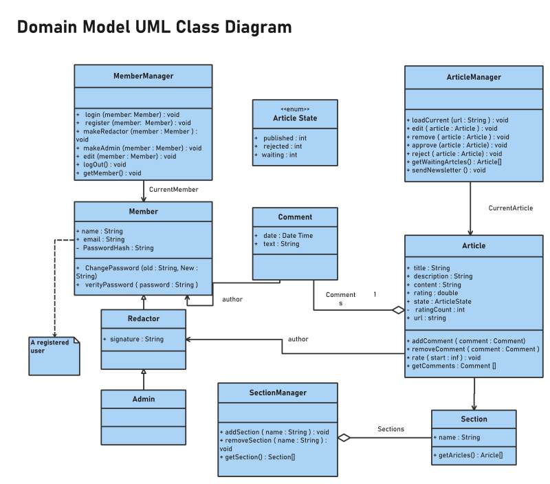
Example 1: UML Class Diagram Example
This UML class diagram example depicts the relationship between various sections of a domain. It is planning the attributes and design of a software class system. With the help of connectors, you can clearly see the data flow from one section to another. The diagram illustrates current members, articles, comments, and authors regarding each system section. With its help, you can quickly understand the overall layout of the system design. The format of this diagram is simple as each box represents a different section, and lines depict the data flow.
Source:EdrawMax Online
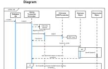
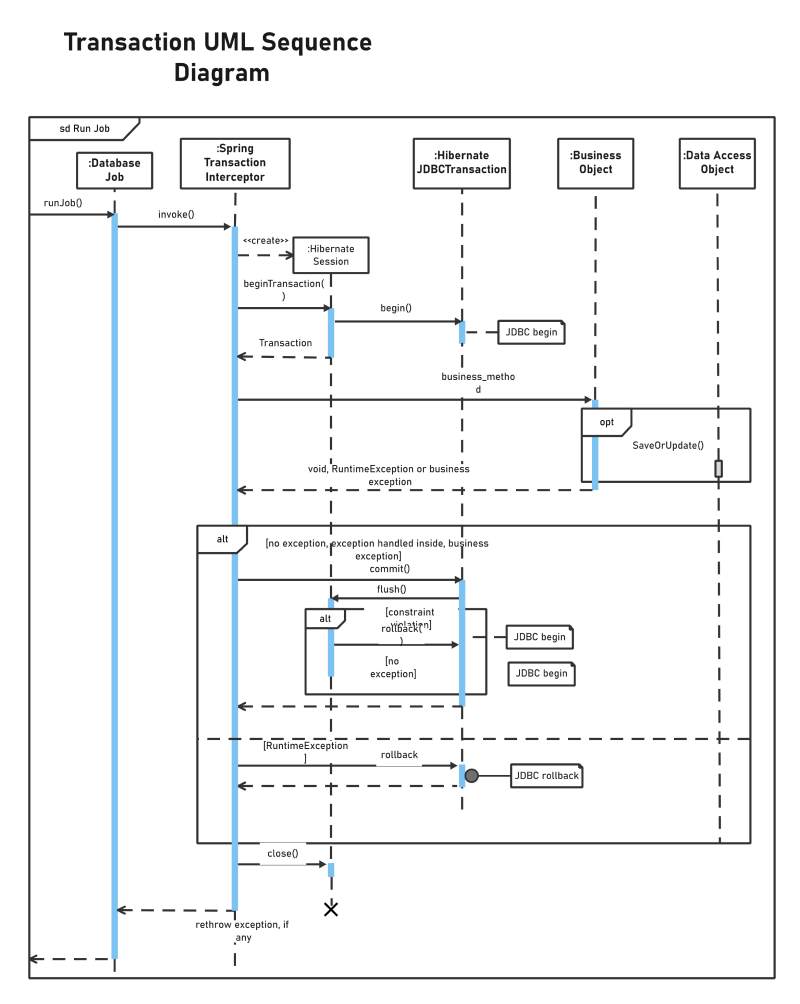
Example 2: UML Sequence Diagram Example
This is a UML sequence diagram example that depicts the transaction management of a java system. You can see from the layout that the diagram focuses on the activities and operations of the system's component instead of modeling each element's position. We use the UML sequence diagram to depict data for a specific time interval and in a sequential manner. The chart lists the components in the same sequence they carry out their operations. It looks a little complicated, but it is elementary to understand as long as the UML follows a particular series.
Source:EdrawMax Online
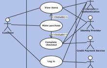
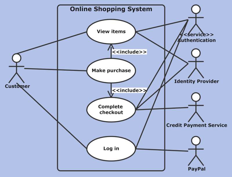
Example 3: UML Use Case Diagram Example
This UML use case diagram example depicts an online shopping system. You can see that the layout of the diagrams in each model is different because there is no specific format of a UML diagram. You can design your system in any way you want by making sure that the UML illustrates a perfect working system. We see the customer on the left side of the diagram, and components of the system are in the middle, and operations related to each element are on the right side. You can easily see the workflow of the shopping system.
Source:EdrawMax Online
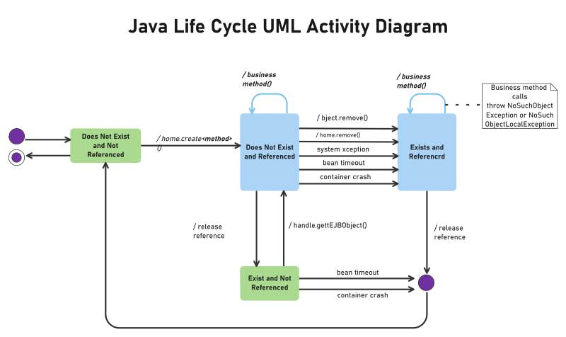
Example 4: Java UML Diagram Example
This is a java UML diagram example that illustrates the system's life cycle of java activities. The diagram visually represents the workflow of business methods in the system using a unified approach. Instead of using lengthy and complicated plain text, UML uses pictures and shapes to document and design a system and its activities. The chart uses arrows and lines to depict the data flow when the systems call any function or carry out any operation. You can use arrowheads to represent workflow direction and use labels to give details about any activity.
Source:EdrawMax Online
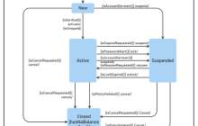
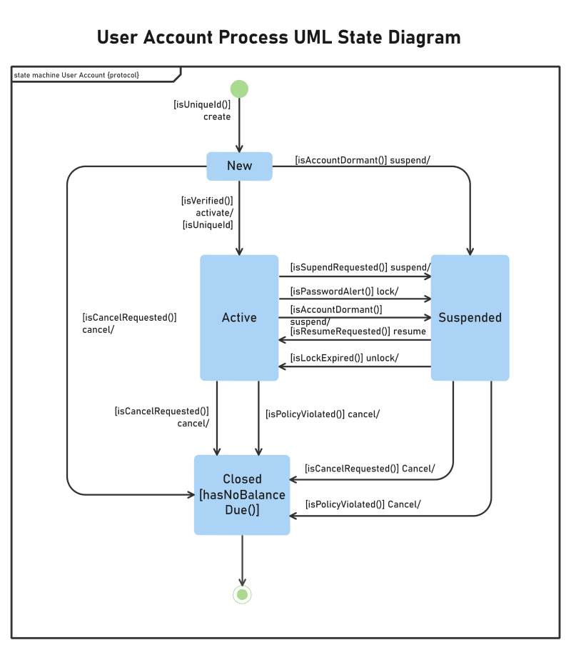
Example 5: UML State Diagram Example
This UML state diagram example illustrates the account state when a customer shops from online stores. There are four essential components in the system, and all operations are mainly based on these components. With a UML state diagram, you can represent event-driven objects and related operations. The chart showcases the process of using a new account for online shopping. The system activates or suspends the account after verifying it, and it also checks the account for any balance dues.
Source:EdrawMax Online
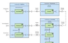
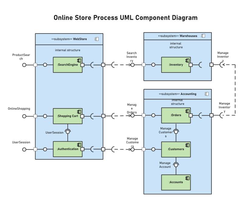
Example 6: UML Component Diagram Example
This is a UML component diagram example that visualizes the store process of an online system. The diagram has three sections, each with various components that carry out specific activities. The workflow is easy to understand, and the chart is mainly labeled to give more details to the reader. The first section is the search system web stores which carry out authentication, search engine, and a shopping cart for the online store. Next is the store's inventory in the warehouse section, and at the end, we got the account section.
Source:EdrawMax Online
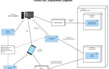
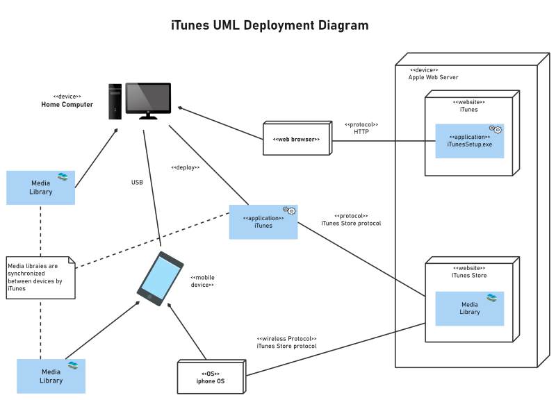
Example 7: UML Deployment Diagram Example
This is a UML deployment diagram example that illustrates the workflow of the iTunes application. In this type of UML diagram, you can clearly understand the deployment architecture of any working system using nodes and connectors. You use this diagram to explain the operations and attributes of a system. It represents components of the system using symbols and icons such as the computer and the mobile icon. Connectors are the lines and arrows that depict the relationship between parts and the data flow.
Source:EdrawMax Online
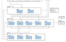
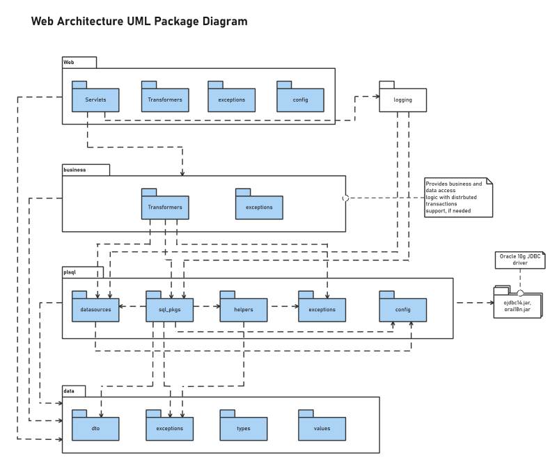
Example 8: UML Package Diagram Example
This UML package diagram example depicts the architecture and connection between layered web system components. We use it to illustrate the dependencies of packages in the system model. You can use this diagram when modeling a complicated system with many elements. You can group UML elements that belong to the same section in a package, and you can use lines and connectors to depict their relationships and operations in the system. If many packages make your diagram complex, then you can even group similar packages in a single package.
Source:EdrawMax Online
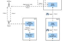
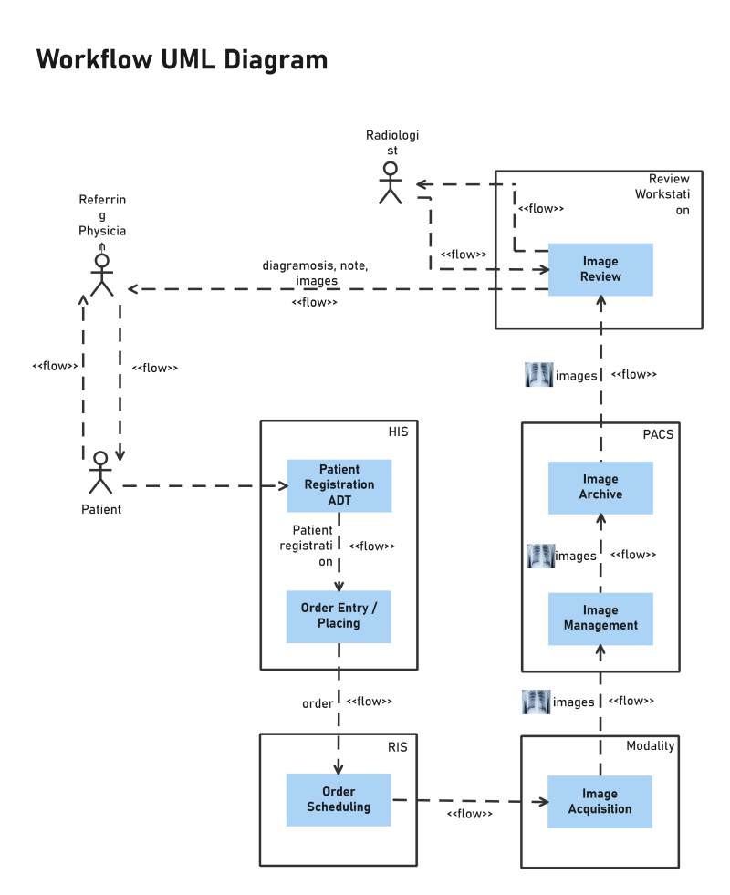
Example 9: Basic UML Diagram Example
This is a basic UML diagram example that visually represents the workflow of a system. It is the most commonly used format of a UML diagram. It is easy to create, and readers can get the general idea while reading it at a single glance. The diagram in the example represents a simple profile integration model. The physician requires a new x-ray to diagnose the patient. The patient first moves to the registration desk and makes an entry. The patient takes an x-ray, and the image goes to a radiologist for review. After that, it goes to the physician, who then explains the patient's condition.
Source:EdrawMax Online
3. Online UML Diagram Maker
There are various formats to create a UML diagram, so you can pick any layout you want that suits your project. Since there are many choices, there are chances that you might choose the wrong format or make mistakes while creating your diagram. EdrawMax Online is the best online UML diagram maker as it comes with a variety of UML professional templates. It also gives you a comprehensive symbol library and various customization tools. You can also find templates for all the diagrams in the above examples in EdrawMax Online. It makes your job easy when many elements and connectors are in the chart.
4. Key Takeaways
UML diagrams are commonly used to model system designs and illustrate process flow in various fields. At first, UML diagrams were only a part of designing a system in software engineering. Still, now with its multiple features, we use these diagrams to depict workflow, behavior, and attributes of components in a system. From our UML diagram examples, you can see that there are many types and formats of a UML. With EdrawMax Online, you can make a perfect UML diagram. You can use its professional templates and various editing tools to make your diagram in no time at all effortlessly. Find more UML diagram examples in the template community.


