Circuit Diagram – Everything You Need to Know
Create a Circuit Diagram on Edraw.AI Online Free Free Download Free Download Free Download Free DownloadWhat is a Circuit Diagram?
A circuit diagram is a typical representation of an electrical circuit drawn graphically. It displays how electrical components are interconnected. Engineers and electricians use it to explain parts and paths of an electric course symbolically. Circuit diagram plays a vital role in the design, construction, and maintenance of electrical and electronic machinery.
Elementary diagram, electrical diagram, and electronic schematic are terms used to refer to a circuit diagram. Circuit diagrams are also pictorial as they use compelling images. Schematic diagram uses industry-standard symbols. We shall look at Circuit diagram in detail in this article.
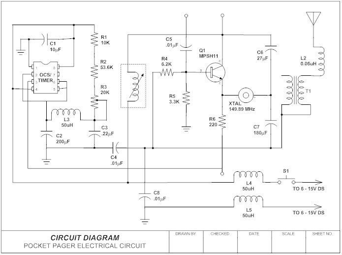
Image Source: Smartdraw.com
Why is a Circuit Diagram Signigicant?
Circuit diagrams play an essential role in the electrical field. Here is why it is vital to have a circuit diagram, especially in the aircraft and nuclear plant industries:
- Personal safety – They alleviate harm/accidents to the personnel working on them through electrocution and explosions.
- Equipment safety – Proper circuit diagrams assist the electrician in getting a better understanding of the design, considering modifications smartly, and adequately explain their work plan.
- Cost-effective – Although it might take time to create the circuit diagram, a final budget plan is drawn afterward, saving the industry cash losses incurred when there is no prerequisite picture of the process.
- Improved output – They are a plan for circuit designs; hence, it is easy to make corrections beforehand, they provide a graphical display of the real arrangement of all entities in a circuit and how electrical wires are connected physically. They act as a guideline for electrical technicians to implement a circuit design.
- Enhanced training – They teach newbies and contractors about how things go in a particular industry. They are a good reference point and make learning simple besides facilitating the continuation of the project by anyone.
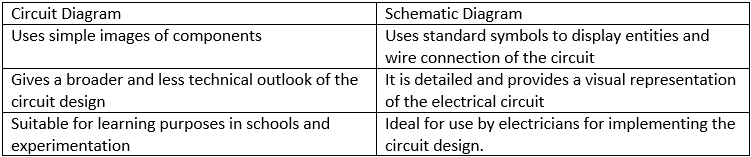
Circuit Diagram Vs. Schematic Diagram
Circuit diagrams also referred to as pictorial diagrams, are not the same as schematic diagrams.
Types of Circuits
A closed-circuit is one with a complete path, while an open circuit has an incomplete path, i.e., not closed. In other words, when you switch off the lights in your room, the circuit becomes incomplete; hence, the bulb doesn’t give light. But when you switch them on, there is the complete connection of the circuit hence the bulb lights.
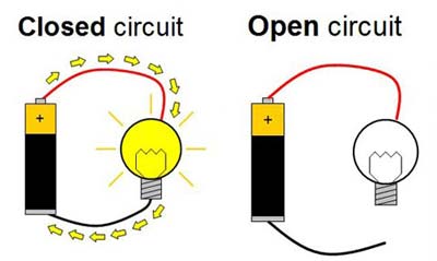
Image Source: completeelectrical.biz
In a series circuit, the connection of components makes the same current flow through all parts of the circuit. The current takes only one path, hence in case of bulbs, when one is missing or gets damaged, the current won’t flow through the rest, and none will turn on.
In a parallel circuit, the electrical entities get arranged in a way that the current has to break before the next connection. The current dives, thus, the components get independently charged. This type of connection is used in houses so that when one bulb burns out. It doesn’t affect the entire lighting of the apartment.
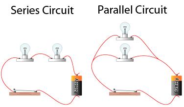
Image Source: completeelectrical.biz
Short circuit lets current travel along the undesignated path. The current is bound to incur minimal resistance; hence, the component that is bypassed by the short circuit can get damaged. The enormous flow of current during a short circuit causes the wires to overheat and may lead to a fire. Thus the need to install circuit breakers and fuse boxes to cut off circuits.

Image Source: completeelectrical.biz
Main Parts of a Circuit
A circuit, regardless of its size or where it is, has four significant parts. These include an energy source, popularly known as AC or DC, a conductor which is the Wire, an electrical load that is the device, and a controller (Switch). Let us look at them in detail:
It provides the voltage and current to power a gadget connected to the circuit. Voltage power sources include batteries of any sort, like those used in cars, laptops, solar panels, etc. They ensure a constant level of voltage to the circuit.
A current power source is ideal for providing a maintained current of energy despite the voltage capacity. Current, measured in amps, gets included in a system to protect the device that provides the electrical load on the circuit. For instance, an LED needs a maintained level of current to prevent it from blowing up or getting damaged.
The Conductor provides the path of the circuit through which energy flows. It is responsible for joining all the other entities of the channel. Just like fluids flow through pipes, the amount of energy need in a circuit determines the measure of the wire that makes up the circuit conductor.
Like any other switch out there, this one also closes (continues) or opens (breaks) the flow of electricity in a circuit. There are various switches like wall switches, key toggles on car keys, pushbuttons, and such biometric tools.
It refers to the amount of energy a device requires to complete a task, be it lighting, heating, or starting a process. The amount of power used up gets measured in watts and gets calculated by multiplying the current in amps and the volts in the particular circuit. Nowadays, pretty much every home has a power-consuming item, be it televisions, motors, etc., all these are load devices.
Circuit Diagram Symbols
The symbols used to make circuit diagrams are standardized on an international level. Every symbol represents a feature of the physical modeling of the device. Hence it is crucial to get what every symbol stands for properly. Next, is a list of the most frequently utilized circuit diagram symbols:
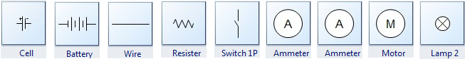
- The Cell – it is the energy source. Its logo is two lines, one long the other short, parallel to each other.
- The Battery –is more than a single cell with the more significant terminal, usually on the left, being + (positive). It looks like a series of long and short parallel lines.
- The Wire – is a media for transporting current from one spot to the other and connects the components of a circuit.
- The Resister – regulates the flow of current and is usually a zig-zag line.
- The Switch – is responsible for the complete flow of current. It is the break in a straight line or the upward diagonal line in a circuit diagram.
- The Ammeter – is for measuring current represented by the letter A in a circle.
- The Voltmeter – is for measuring voltage and is a circled letter V in a circuit diagram.
- The Motor – is a transducer for converting electrical energy to kinetic power. Its symbol is a circled M.
- The Lamp – is the component that changes electrical energy to light.
Examples of Circuit Diagrams
Next, we will look at circuit diagram examples to enhance your understanding of them.
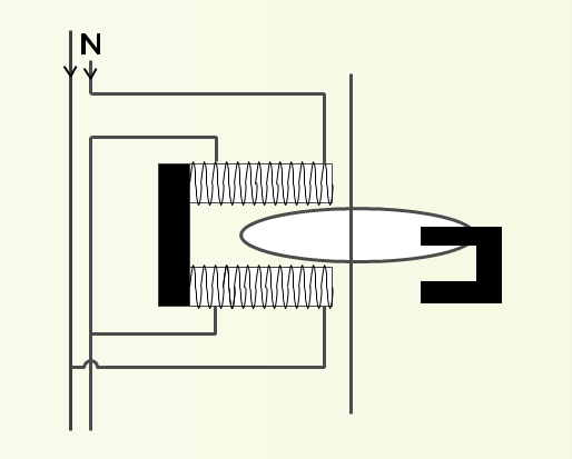
It is also known as a motor meter. The total power used over a certain period is energy and measured by a motor meter. Furthermore, motor meters are also used in power supply lines to houses to measure the amount of energy used in both DC and AC circuits. Energy meters get usually calibrated in kilowatt-hour, where one kilowatt-hour is equal to the amount of electricity needed to provide 1000 watts of power for one hour.
In a motor meter, there is an aluminum disc that rotates non-stop during power consumption. There are also pressure and current coils such that when the voltage gets put on the pressure coil, the current flows through it and produces flux, which releases toque onto the disc. This torque acts on the drive causing the aluminum disc to rotate. The rotation is proportional to the amount of energy used. It is then recorded on the energy meter.
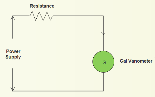
It is a black box consisting of electrical circuits that enable one to restart pretty much any form of electrical wiring or gadget. It is also known as a volt-ohm meter or VOM and is made up of a myriad of numbers, dials, and switches that can be quite confusing.
It is swift to check whether batteries used in various devices are still functional. A volt-ohm meter comprises a galvanometer connected in a series style to a resistor. You can measure the current flow, i.e., the voltage across the circuit, by joining the ends of the VOM across the channel. It is an excellent tool to have in your toolbox collection for measuring electricity.
How to create a circuit diagram with Edraw
Finally, after looking at the theoretical part of a circuit diagram, we get to create one using EdrawMax online tool. You can access it easily from https://www.edrawmax.com/online/.
Before jumping to the thrilling part, you first need to:
Take a close look at the Circuits and Logic Template provided in Edraw. The tool provides you with built-in electrical diagram symbols, electronic circuits, logic circuits, and similar technical diagrams. All you have to do is double click the template from Engineering Category on the main window and get to the drawing page.
Now, follow these simple steps to draw a circuit diagram:


You can then:
Print: go to the File menu and tap on Print for print options. or
Export: go to File Menu then select Expo rt & Send for Export options. You can share the circuit diagram to a variety of formats like Microsoft Office, PDF, etc.