How to Read a P&ID Drawing Quickly and Easily
Create a P&ID Drawing Online Free Free Download Free Download Free Download Free DownloadWhat is a P&ID?
P&ID stands for the Piping and Instrumentation Diagram. It is an in-depth diagram which comprises of process equipment, piping, control devices, and instrumentation in a visual form. The P&ID drawing is usually used in the Process Industry and Engineering field. Piping and Instrumentation diagrams are useful instruments when it comes to the design, modification, and maintenance of an engineering process. It is also known as PEFS (Process Engineering Flow Scheme).
As you may know, a P&ID drawing is a complex chart; hence, it is quite hard to understand them, especially if you are a non-experienced individual in this field. Today, we will tell you how you can read a P&ID drawing even if you are not an expert. Edraw Max is a graphics tool that performs well in creating many different types of charts, graphs, and diagrams. It can also be used to create or read P&ID drawings.

Image Source: pixabay.com
Why Use P&IDs?
As stated earlier, P&ID drawings are used in engineering and other process industries like Gas or Oil refineries. Here are some reasons for using P&IDs extensively:
- Training workers
P&ID illustrations are commonly used by engineers, operators, and field technicians to demonstrate different processes in detail. The drawings help them keep track of the connection between the instrumentation. Hence, People use P&IDs to train the workers and contractors who will be responsible for the construction and manufacturing jobs.
- Designing Plants
Engineers use P&IDs to design manufacturing plants. They plan and construct different processes of a physical plant. Hence, P&ID drawings help them in designing and planning more systematically.
- Safety and maintenance
Once a process or plant is complete, P&IDs can be used to study different mechanical and chemical steps and find out the cause in case something goes wrong. Hence, they can be used for the safety and maintenance of a process.
- Cost Estimation
P&IDs are also used for project capital cost estimations. It gives a clear picture of all the components and instruments that will be needed to build a particular process. Therefore, the P&ID is also used for specifications in development contracts and estimation of process costing.
How to Read a P&ID Drawing
To help you learn how to read P&ID like a pro, here is our guide using P&ID diagram symbols by Edraw Max.
Step 1 – Open Edraw Max
Launch your browser and go to Edraw Max Online using this link: https://www.edrawmax.com/online/
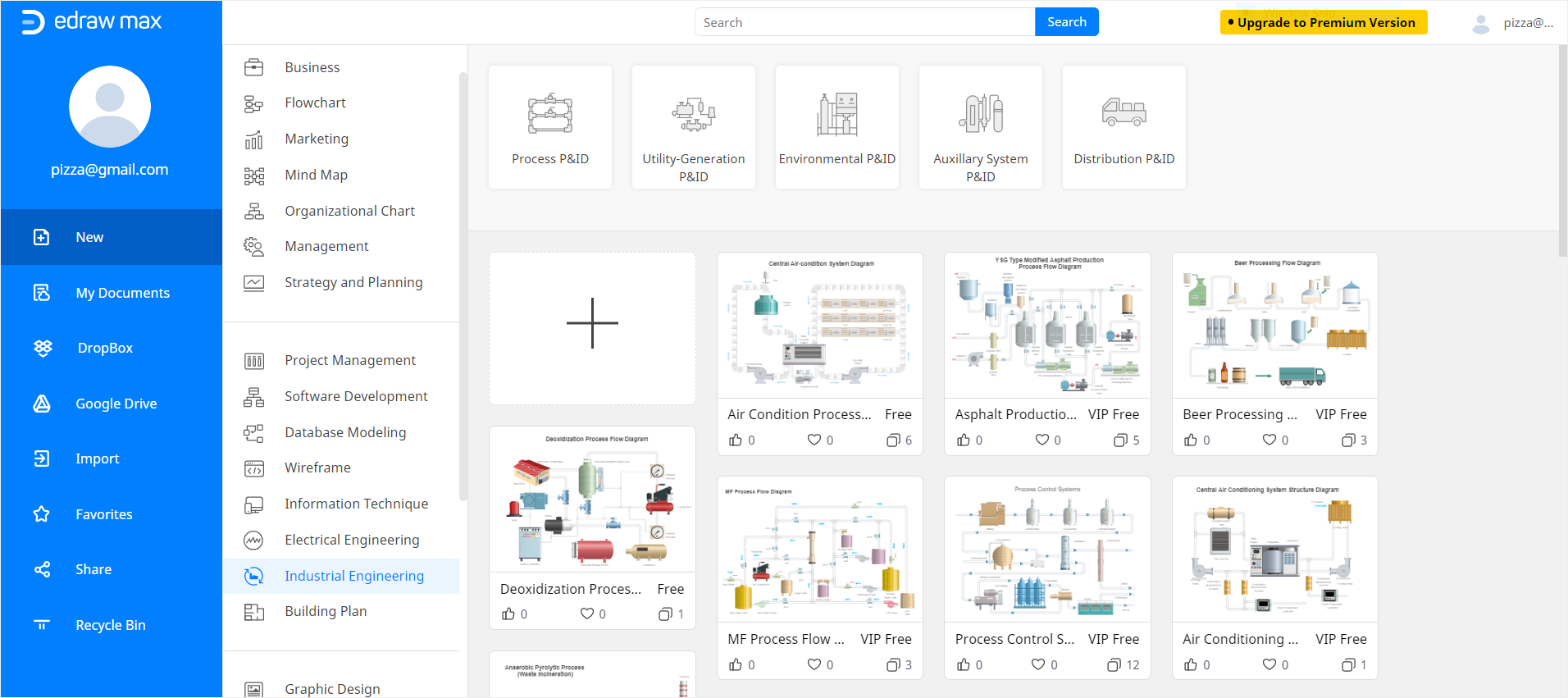
Step 2 – Select Industrial Engineering
To read a P&ID drawing, you must know what each symbol means and how each symbol is constructed. For this, you need to go through different P&ID drawing symbols. To find P&ID templates in Edraw, scroll down on the navigation pane on the left side of the screen and click on Industrial Engineering.
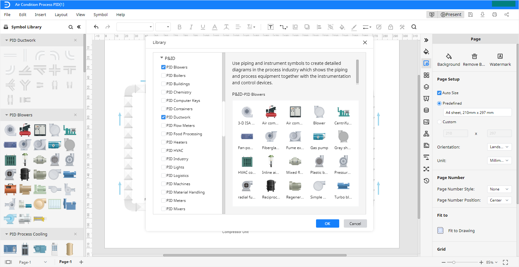
Step 3 – Find Symbols
Open a new tab of Edraw Max editor, go to the Symbol Library on the left side of the screen in the new tab. Click on the icon next to Symbol Library and wait for the pop-up screen to launch. Scroll down and select P&ID. Edraw Max will give you different types of P&ID symbols. You can use these symbols to understand what they mean and how they connect. Once you have managed to do this, you will be able to read a P&ID drawing.
Step 4 – Know P&ID Symbols
Being able to read a P&ID drawing needs you to have an in-depth knowledge of P&ID symbols. Because using simplified and united symbols and vivid equipment icons, people are more likely to know the P&ID drawings and what they represent.
All the below P&ID symbols are existing in the symbol library of Edraw Max Online.
- Equipment symbols: Comprise of all other symbols that don’t belong in different categories. These are miscellaneous hardware.
- Piping Symbols: Comprise of different types of pipes that transfer fluids.
- Vessel Symbols: Represent containers that are used to store fluids.
- Pump Symbols: Consist of devices that move fluids in and out of a container using changes in pressure.
- Instrument Symbols: Show the devices that control and measure different quantities like pressure, temperature, angle, etc.
- Valve Symbols: Illustrate the devices that control passageway in piling systems to direct, regulate, and control the flow of fluids.
More Editable P&ID Examples
Now, you know how to read P&ID drawings, and you can also learn how to draw them quickly. Here are some editable P&ID examples from Edraw Max, which you can use.
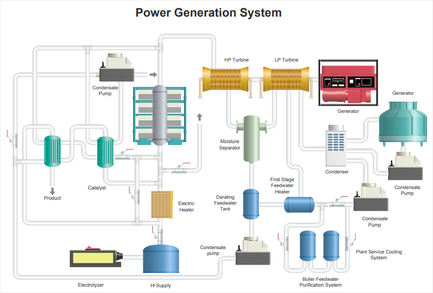
Power Generation P&ID Example – Use this customizable power generation P&ID template to plan a presentation, read workflow analysis, and document a process.
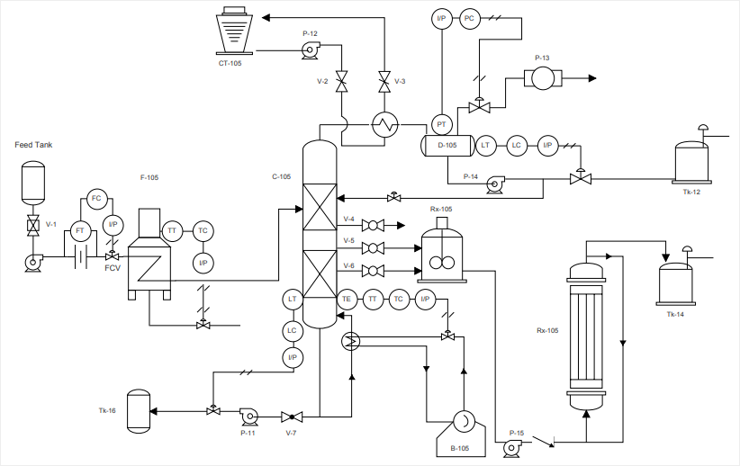
Processing P&ID Example – Use this processing P&ID template to document and read different P&ID processes in a short time.
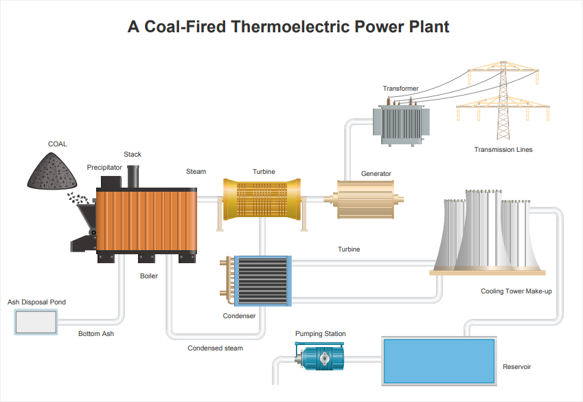
Power Plant PID Template – Use this power plant P&ID template to figure out how the power plant works or help you in designing a similar one.