Wiring Diagram – A Comprehensive Guide
Create a Wiring Diagram Online Free Free Download Free Download Free Download Free DownloadWhat is a wiring diagram?
A wiring diagram is a visual representation of components and wires related to an electrical connection. This pictorial diagram shows us the physical links that are far easy to understand an electrical circuit or system. One wiring diagram can signify all the interconnections, thereby signaling the relative locations. The use of a wiring diagram is positively recognizable in manufacturing or electrical troubleshooting projects. It can prevent lots of damage that even derail an electrical plan.
In this article, we will learn some interesting facts about the wiring plans, their importance, and the useful online tool, i.e., EdrawMax, to draw them quickly.
Why do we use wiring diagrams?
Wiring diagrams are highly in use in circuit manufacturing or other electronic devices projects. The layout facilitates communication between electrical engineers designing electrical circuits and implementing them. The pictures are also helpful in making repairs. It shows whether the installation has been appropriately designed and implemented while confirming the safety regulators.
A wiring diagram can also be useful in auto repair and home building projects. For example, the proper location of light fixtures and electrical outlets can be easily by a home builder to avoid costly defaults or building any code violations.
Benefits of Wiring Diagrams:
Drawing a wiring diagram offers several advantages, as given below.
- The diagram is easy to share even electronically.
- The process of creating a diagram is fast and allows for conventional construction.
- Access to hundreds and thousands of wiring symbols makes the diagram more efficient to be understood.
- The diagram is simple to edit as per the different conditions.
- The proper tool provides precise placement of symbols, which is an impossible task to be done by hand or other means.
Type of wiring diagram
With the use of different symbols, an electrical wiring diagram mainly consists of three main types. Everything related to an electrical system can be shown on one of the charts to ensure that interconnections are working correctly. Its three main kinds are as follows.
Schematic diagrams show the circuit flow with its impression rather than a genuine representation. They only provide general information and cannot be used to repair or examine a circuit. The functions of different equipment used within the circuit get presented with the help of a schematic diagram whose symbols generally include vertical and horizontal lines. However, these lines are known to show the flow of the system rather than its wires.
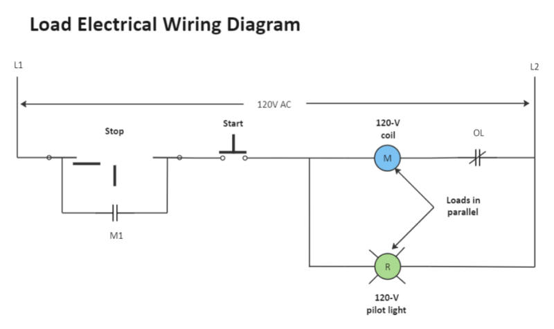
A wiring diagram represents the original and physical layout of electrical interconnections. Wiring on the picture with different symbols shows the exact location of equipment in the whole circuit. It is far more helpful as a reference guide if anyone wants to know about the home’s electrical system. Its components are shown by the pictorial to be easily identifiable.
It is the least efficient diagram among the electrical wiring diagram. They are often photos attached with highly-detailed drawings or labels of the physical components. A pictorial doesn’t even make an effort to be shown clearly or effectively. A person with a strong knowledge of electrical wiring diagrams can only understand a pictorial.
Wiring Diagram VS Schematic Diagram
It is common to mistake a wiring diagram for a schematic diagram or vice versa. These diagrams visually represent connections and circuits, but their functionality is entirely different. A wiring diagram illustrates the physical components of an electric circuit. On the other hand, a schematic diagram depicts the function of the circuit without any concern for the circuit's physical layout. The table down here will help you better understand the difference between both diagrams.
| Items | Wiring Diagram | Schematic diagram |
| Definition | A wiring diagram shows or conveys the wiring connection between all components in a good way. So that anyone can prototype. | A schematic diagram is a diagram of any circuit that shows clear connections and in standardized form between components. A schematic diagram shows all components in the diagram and components values and connection details in the understanding form. |
| Purpose | It's used to represent diagrams graphically. | It's used to represent diagrams in circuit form. |
| Types | Wiring Diagram, Pictorial Diagram, Layout Diagram, etc. | Block Diagram, Logic Diagram, Single Line Diagram, etc. |
| Most use for | A wiring diagram is mainly used in motor control installations and designing electrical circuits. It visually represents the outline for all physical components of the system and their respective positions. | A schematic diagram is mostly used in the electrical industry. For any maintenance and repairs in the system, schematic diagrams are the best option as they are simple and easy to understand. |
How to read a wiring diagram: Symbols you should know
To read a wiring diagram, you should know different symbols used, such as the main symbols, lines, and the various connections.
The standard or fundamental elements used in a wiring diagram include power supply, ground, wire and connection, switches, output devices, logic gate, resistors, light, etc. There is an article to introduce electrical symbols.
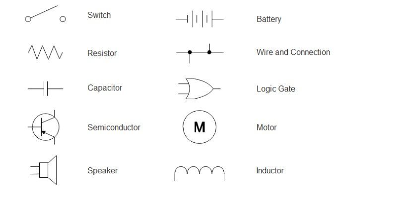
- Switch - A switch in an electrical wiring diagram includes sub-symbols such as a push-to-break switch, push-to-make switch, 2-way switch, DPST switch, DPDT switch, etc.
- Battery - A battery represents more than one cell to indicate electrical energy. Moreover, it works on constant voltage.
- Resistor - The resistor shows the restriction to the flow of current. It is used along with a capacitor in a timing circuit.
- Wire and Connection - Wire and Connections symbols include the wire, wire joined, and the one not joined. Wires joined generally form two-T junctions, whereas the wires not joined are simply the crossing wires not connected.
- Capacitor - A capacitor is a storage unit of electric charge. The symbol is used with a b and can also be shown as a filter to pass AC signals and to block DC signals.
- Logic Gate - A logic gate is a kind of process signal used to represent True (High, 1, on, +Vs) or False (low, 0, off, OV). It also contains sub-symbols such as AND, NOT, NAND, NOR, and OR.
- Semiconductor - Semiconductor symbols are smart and commonly used for indicating components such as Bipolar, MOSFET, Controlled Rectifier, Controlled Switch, Diode, Diac, Triac, etc.
- Motor - A Motor represents a transducer by which electrical energy gets converted to kinetic energy.
- Speaker - A speaker is a digital input turned into analog sound waves. It is one of the essential parts of different products like telephones and TVs.
- Inductor - It is a component of an electric circuit possessing the inductance. It also includes different symbols such as position transmitter inductor, half inductor, mutual inductor, etc.
Wiring Diagram Examples
You can find out all wiring diagram templates in EdrawMax Template Community.
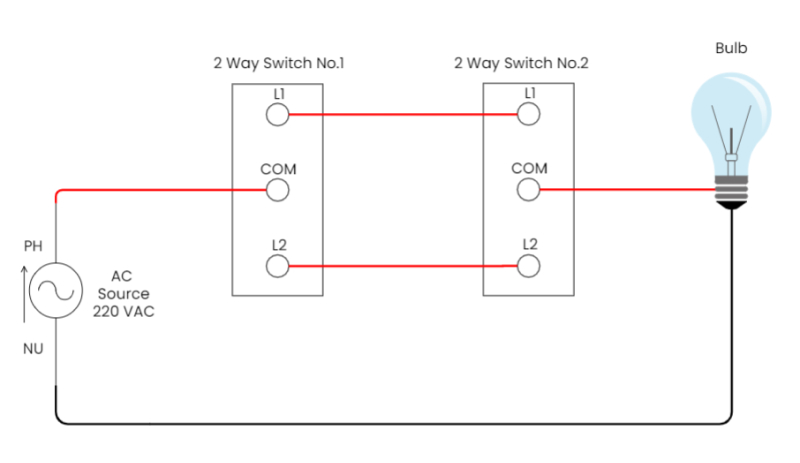
In a two-way switch, there are two, one-way switches combined in one. One of the terminals can be connected to either of the two, but not both at the same time. The advantage of a two-way switch is the ability to control a single device from two separate locations. Uses of Two Way Switch? A two way light switch is a switch that can be used in conjunction with another two way light switch to turn a light (or lights) on and off from more than one location. 1.Staircase 2.Bed Room 3.Bathroom 4.Godown
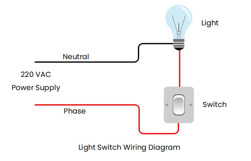
Making a wiring diagram for a light switch is very easy. In this diagram, we have to use a single-pole switch that can turn on and off our led. Firstly, we have to connect our phase wire to one of the ends of the switch terminal then another terminal of the switch to light. The remaining neutral wire is connected to the other end of our led light. So this is the simple wiring diagram of a led switch. For more details, the circuit diagram is given below.
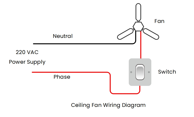
Creating a wiring diagram for a ceiling is also very easy. In this diagram, we have to use a fan regulator that can turn on and off our fan as well as control the speed of the fan. Firstly, we have to connect our phase wire to one of the ends of the regulator terminal then another terminal of the switch to the fan. The remaining neutral wire is connected to the other end of our fan. So this is the simple wiring diagram of a ceiling fan. For more details, the circuit diagram is given below.
How to draw a wiring diagram with Edraw?
After gaining the best understanding of the main concept, we should now continue with the knowledge on how to draw a wiring diagram with one of the best online tools – EdrawMax. To make a wiring diagram online, head over to the official website of Edraw, and continue with the following steps.
Step 1: The first step is to sign up on EdrawMax Online. For this, you need to use valid email id and a password.
Step 2: Select Electrical Engineering and Basic Electrical. As the creation of wiring diagram is an electrical concept, you need to select Electrical Engineering from the side panel. It will lead you to different options on the main interface from where you have to go for Basic Electrical.
Step 3: Create a template. The next step is to create your template. Firstly, you need to select + icon of Basic Electrical. This selection will lead you to the main interface of diagram creation as follows. Step 4: Make your wiring diagram from different tools.In this window, you can create your wiring diagram by choosing different wiring diagram symbols from the symbol library. There are various symbols available such as transmission path, qualifying symbols, semiconductor devices, switches and relays, and other necessary electrical symbols.
Watch this video to learn more. If the video doesn't play, please visit it at YouTube.
Wiring Diagram Maker
We use a wiring diagram to visualize the wires connections and devices in an electrical circuit in a simple way. We use lots of symbols and icons to represent various components in the circuit. You need the best wiring diagram maker EdrawMax Online to create a perfect wiring diagram. It comes with many professional templates that you can customize and edit to create a new diagram. It also gives you many customization tools and a comprehensive symbols library that helps you make your diagram from scratch. Creating a diagram with EdrawMax Online makes your job effortless, and you can do it in a few minutes.


