Package Diagram Explained
Create a Package Diagram Online Free Free Download Free Download Free Download Free Download1. What Is a Package Diagram in UML?
In UML(Unified Modeling Language), a package diagram is a pattern for grouping elements and defining their interdependencies (packages). The main goal of package diagrams is to simplify the complex class diagrams that can be used to group classes into packages. These groups help define the hierarchy. It is worth noting that the UML elements in the package are based on logical relationships.
A package diagram is a set of defined elements that are semantically linked and potentially changed together. It is the grouping of model elements and the definition of their relationships. To some extent, a package diagram is a container for model elements. However, the package may contain the entire diagram, a separate component name, or even no component.
2. Application Scenarios of Package Diagrams
A package diagram is used to arrange the components/elements of a high-level system, so packages can be used for large system organizations that contain diagrams, documents, and other project goals. The idea is to create a systematic representation of a set of instructions or procedures. Therefore, you may use the package diagram to:
- Simplify complex class diagrams and organize classes into packages
- Define packages as file folders and use them on all of the UML diagrams
- Define the hierarchical relationships (groupings) amongst packages as well as other packages or objects
- Create a structure and visualize complex processes into simplified packages in technology, education and other fields, in order to visually depict non-linear processes.
3. Package Diagram Symbols

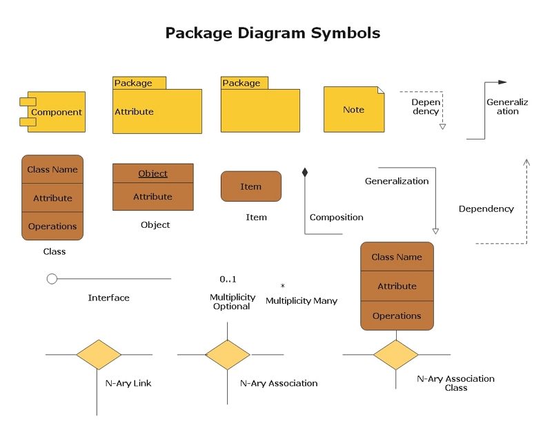
The package diagram follows the hierarchy of nested packages. Thus, the package name should not be the same in the system, but classes in different packages may or may not have the same name. For each UML, a package can contain any element, that is, classes, interfaces, modules, nodes, use cases, diagrams, and other packages grouped into it. Any elements displayed in a package are defined and elaborated in the same package. And show the relationship between them. When we destroy the package, it also destroys all existing components in it.
- The package appears as a rectangle at the top with small labels.
- The name of the package appears on the TAB or in the rectangle.
- Dashed arrows indicate dependencies.
- Interface - is the specification of behavior or pattern.
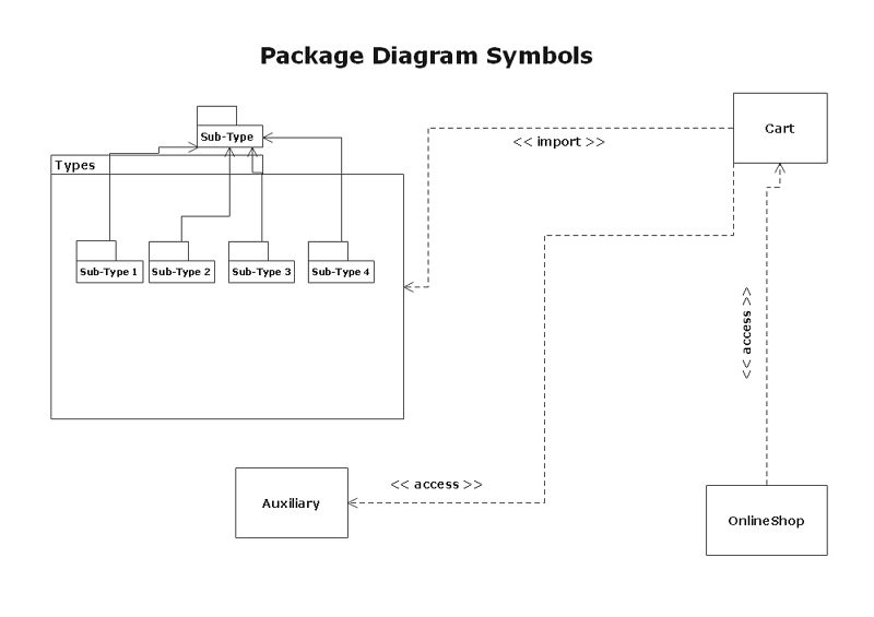
- If a change in the other package is likely to lead to a change in the first package, then one package will depend on the other.
- Object - is an instance of a class. It used to represent an item.

- Access - Access is a private form of import, where the imported element will be added to the namespace but will not be visible outside of it.
- Import - Import is a public command. The imported element will be added to the namespace and will be visible outside of it.
-
Subsystems are used for system decomposition, which can be represented by various parts of the system according to specification and implementation.
- An external perspective of the resources provided by the subsystem.
- Internal view, indicating the subsystem implementation.
- There is a mapping between these two factors.
4. Package Diagram Examples
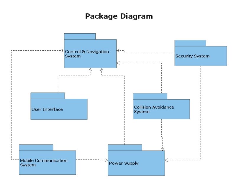
Diagram 1: Control & Navigation System
The package diagram shows the interdependencies of the package and the process for each package. This diagram represents a package diagram with six different packages, representing the complex subsystem used to meet the requirements.

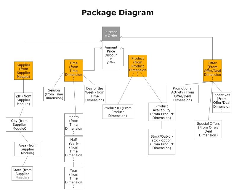
Diagram 2: Purchase Order
In this diagram, the "purchase order" process is simplified by a package diagram. The use of UML packages helps to bring this model to a more comprehensible level.

5. Key Takeaways
In UML package diagrams, packages are created to separate model elements and components into consistent units or systems. These diagrams simplify systems like access control, model navigation, configuration management, and other semantic considerations.
Package diagrams can illustrate both structure and dependencies between subsystems or modules. By showing different views of a system, for example, as a multi-layered (aka multi-tiered) application - multi-layered application model. The key element of a package diagram is that it is logical and every element, group, class present in the diagram connects in a sequence, logically.


