What Is Ladder Diagram
Create a Ladder Diagram Online Free Free Download Free Download Free Download Free Download1. What Is a Ladder Diagram?
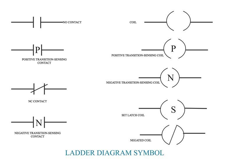
Ladder diagrams are advanced schematics widely used to record logic structures for industrial controls. These are called ladder diagrams because they mimic a ladder, with two vertical rails (supply power) and as many "rungs" (horizontal lines) as there are to represent control circuits.
The load device (lamp, relay coil, solenoid coil, etc.) is drawn almost always on the right-hand side of the rung in ladder diagrams. Although it doesn't matter electrically where the relay coil is within the rung, it does matter that the end of the power supply of the ladder is grounded, for stable operation.
2. Application Scenarios of Ladder Diagrams
- Every system in the relay rack will be depicted with a symbol on the diagram of the ladder indicating the relations between such devices. Furthermore, other things beyond the relay rack, such as pumps, heaters, and so on, will also feature on the schematic of the ladder.
- Ladder logic has developed into a programming language, describing a system through a graphical diagram based on the relay logic hardware circuit diagrams.
- Ladder logic is used to build a programmable logic controller (PLC) software and is used in industrial control applications.
- For basic yet essential control systems or for reworking old hardwired relay circuits, Ladder logic is useful.
- This has also been used in very advanced automation systems as programmable logic controllers have become more sophisticated.
- Ladder logic should be described as a language focused on rules, rather than a language of procedures. A ladder "rung" represents a rule.
3. Benefits of Using a Ladder Diagram
- Intuitive and self-documenting. A ladder diagram provides superb schematic interpretation focused on well-understood principles of circuit architecture.
- The learning curve to get going with a ladder diagram is very small because of the accessibility of the environment; simple programming skills grow rapidly.
- This has made the ladder diagram especially common for applications that involve staff without technical experience to repair or manage, like certain electricians or plant technicians.
- The ladder diagram is intended to replicate electrical circuits, it is a perfect way of reflecting abstract logic of course. A ladder diagram is pretty intuitive for digital logic.
4. Why Is a Ladder Diagram Used for PLC Programming?
Ladder logic is a programming language used for PLC (Programmable Logic Controller) programming. It is a graphical PLC programming language which uses ladder diagrams to express logic operations with symbolic notation, much like the rails and rungs of a typical relay logic circuit.
In order to bring industrial automation applications, it is used by engineers and electricians to execute mathematical, linear, measuring, pacing, and arithmetic functions. It is a common process from which to program a PLC. Ladder logic programming is still used now since the basic concepts of system and process control are still the same.
5. How To Read a Ladder Diagram?
Microprocessors like those used in PLC's and personal computers function at a binary code level. You've read of the word 'neutral' presumably. This applies to the idea that in one of two States, things should be conceived about. Can describe the states as:
- 1 or 0
- Real or Negative
- Tall or Low
- On or Off
- Yes or No
The ladder logic uses symbolic expressions and a graphical editor to write and read ladder diagrams which make it easier for us humans to understand. If we convert a real-life occurrence into ladder language we will symbolically articulate it in the form of a typically open communication (NO). This occurrence may be anything like clicking a button or triggering a limit shift.
6. How to Create a Ladder Diagram Online
The rails in a ladder diagram depict the supply wires of a regulating relay logic circuit. On the left line, there is a positive voltage supply track, and on the right side, a negative voltage track.
In a ladder diagram, the logic flow is from the left-hand rail to the right-hand rail. There are seven fundamental aspects of a ladder diagram which are important to learn when applying a ladder logic system in a PLC. They are names and statements concerning lines, rungs, inputs, outputs, logic expressions, address notation/tag names. Some of these are essential, and some are optional.
- Rails In a ladder diagram there are two rails which are drawn as vertical lines going down the foremost ends.
- Rungs The rungs are drawn horizontally and link the rails to the statements of logic.
- Inputs The inputs are actual control acts such as pushing a push-button or activating a cap switch.
- Outputs Outputs are electronic machines which are turned on and off like an electric motor or a solenoid lever.
- Logic Expressions The logic expressions are used to formulate the desired control operations in combination with the inputs and outputs.
7. Ladder Diagram Example
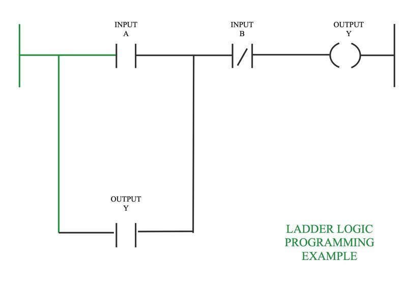
The above diagram depicts a ladder logic programming example, illustrating an input/output circuit.
8. Key Takeaways
The Ladder diagrams (sometimes called "ladder logic") are a type of electrical notation. This symbology is sometimes used to demonstrate the interconnection of electromechanical switches and relays. A digital depiction of the features of the programme.
EdrawMax is a conceptual diagramming program that helps construct the flowcharts, hierarchical charts, mind maps, network diagrams, floor plans, and ladder diagrams. All shapes and clipart are vector format design, which means your ladder diagram will never get blurred, irrespective of what size you change it to.


