What is a P&ID – Beginner’s Guide
Create a P&ID Online Free Free Download Free Download Free Download Free Download1. What is P&ID?
Abbreviated as P&ID, a piping and instrumentation diagram is an articulate drawing of a processing plan that entails the piping and process equipment with its instrumentation and control machinery. It displays the piping and associated parts of a physical process flow. Such diagrams are famous in the engineering field.
The piping and instrumentation diagram has a close relation to the process flow diagram (PFD) that explains a rather typical flow of plant processes concerning major equipment of a plant facility.
2. What Does a P&ID Include?
There is no ideal standard concerning the structure of P&IDs per se. A group of process industry owners and engineering construction contractors in the industry laid out many must-haves in a piping and instrumentation diagram in PIC001: Piping and Instrumentation Diagram Documentation Criteria. Below is what a P&ID should entail:
- Mechanical machinery named and listed numerically
- All valves and their identifications
- Process piping, sizes and identification
- Vents, drain, special fittings, sampling lines, reducers, increasers and swagger under miscellaneous items
- Permanent start-up, flush edges and flow directions
- Interconnections reference, control inputs, and output interlock
- Seismic category and annunciation inputs
- Computer control system input
- Vendor and contractor interfaces
- Identifications for outsourced components and subsystems
- The estimated physical sequence of the equipment and its rating or capability.
3. Basic P&ID Symbols
Like all other professional diagrams, P&IDs has standard shapes and symbols. Based on the industry and manufacturer, there is a wide variety of symbols. Let us look at some of the most famous symbols suitable for smooth functioning across the industry. There is an article to introduce p&id symbols.
Equipment in P&ID entails different units that don't fit into other groups. These include hardware such as compressors, conveyors, motors, turbines, vacuums, and related mechanical tools.
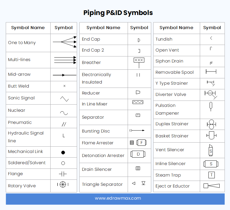
A pipe is a tubular vessel made from plastic or metal for transporting liquid or gaseous substances. In this section, there are one-to-many pipes, multi-line pipes, separators, etc.
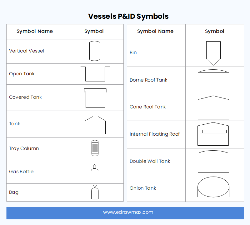
A vessel is a storage container for fluids. Vessels are known to change the characteristics of the fluid contained in them. These are tankers, columns, cylinders, bags, etc.
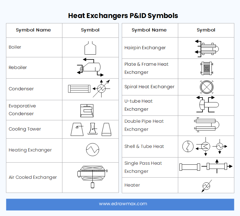
A tool modeled to sufficiently transfer heat from different regions or mediums is known as a heat exchanger. Such devices are boilers, condensers, etc.
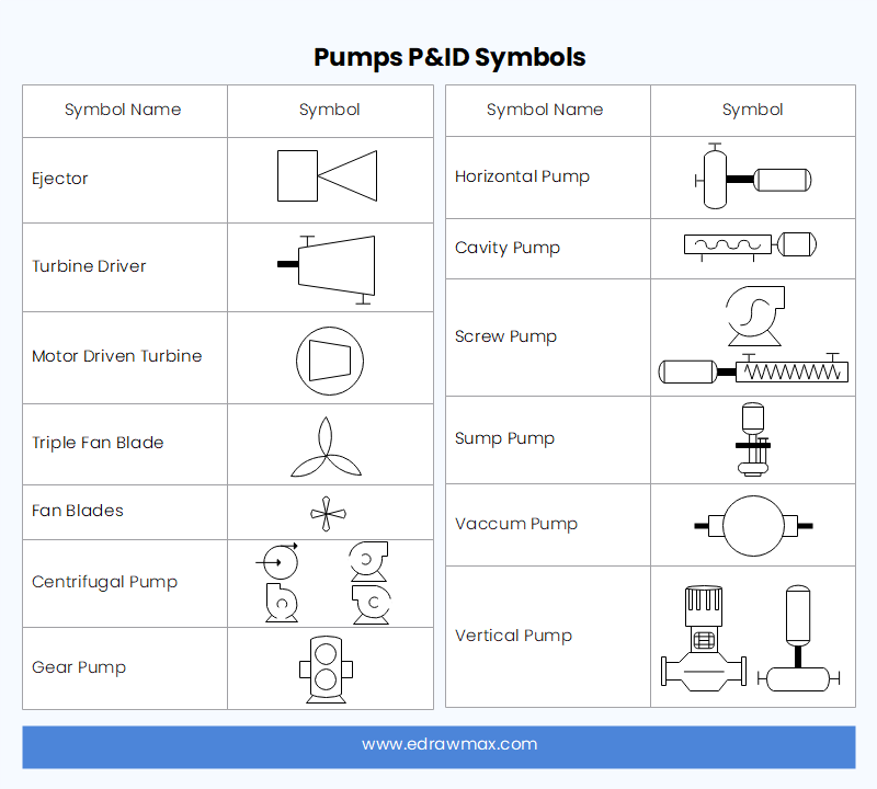
To move fluids in and out of other objects, you need a pump. It uses suction or pressure to raise, compress, or move the fluid. This section consists of pumps and fans.
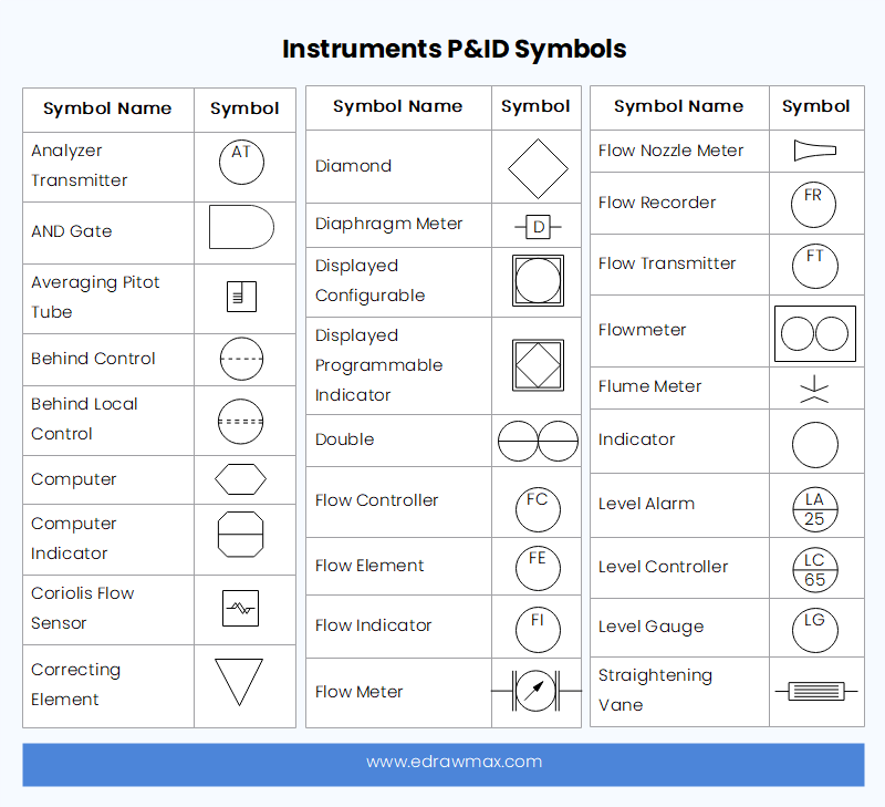
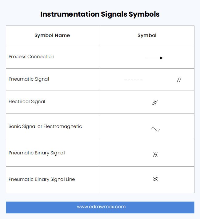
An instrument is a tool for measuring or controlling quantities like temperature, flow, angle, pressure, etc. In a P&ID, they include indicators, transmitters, recorders, controllers as well as elements.
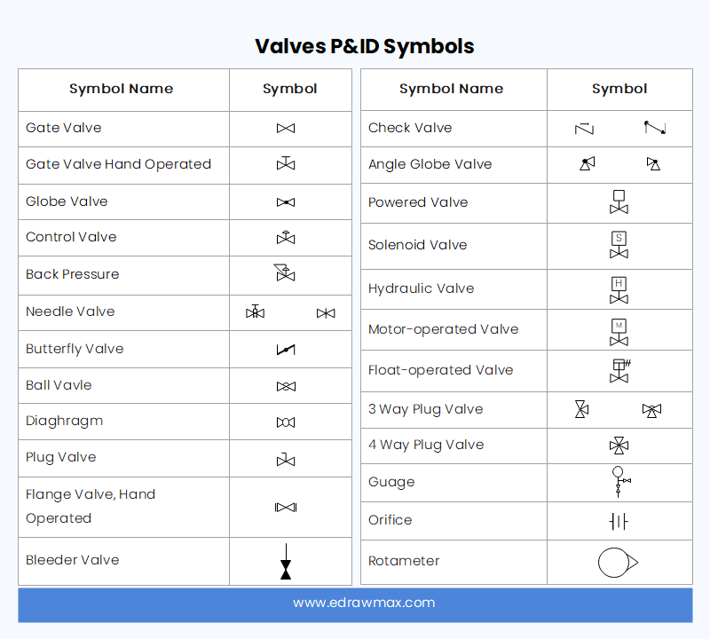
Like the valves in our hearts, they are designed to regulate, direct, or control the flow of a fluid through closing, opening, or slightly blocking passageways in piping set up. In this category, there are rotameters, orifices, and other kinds of valves.
Those are the most basic and vital symbols and shapes in P&IDs. For more image and SVG files, you can import them and create a personalized P&ID library.
4. Purposes and Benefits of P&IDs
To maintain and modify a process effectively, you need a P&ID graphical representation. It provides the foundation for the development of system control blueprints, such as Hazard and Operability Study (HAZOS), during the design stage.
Furthermore, P&ID is crucial in facilitating the designing of:
- Schemes for control and shutdown
- Requirements for safety and regulation
- Sequences for start-up
- Operational details and understanding
5. P&ID Drawings Use Cases
Process system development: P&ID is a schematic drawing that gives a primary visual representation of a process control system. It shows the essential details and information related to the conceptual design process with reality. P&ID diagrams depict the connection between piping, equipment, vessels, and process components. It is an essential part of the development process as it involves detailed engineering.
Safety of system design: One of the priorities during the development process is the implementation of safety features. Many hidden hazards affect the proper manufacturing of a process plant if they are not dealt with at the early stages. P&ID drawing helps designers figure out any possible risk that might create some issues in the development process. The drawing depicts the process and environment of the plant to avoid hazards.
Management of Change: A P&ID diagram is the best way to look for the solution whenever some unexpected issues come out during the development process. It is an essential engineering document that details various processes and materials used to manufacture a plant. Management of change can only change the design to remove the issues with P&ID documents.
Plant Maintenance and Modifications: Some of the materials and process components used in installing a plant start to wear out after some time. There are also some sections of the plant that might need modifications over time. P&ID plays a vital role during the whole maintenance and modification process. It also keeps track of the changes made to the original document for future reference.
6. P&ID VS. Process Flow Diagram (PFD)
The details in piping and instrumentation diagrams are directly proportional to how intricate the design is. A PFD is a simple display of the model, basically a skeleton of the process.
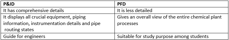
Similarities
- They are chemical/process drawings used in the engineering field;
- They provide sufficient details required during the various chemical/process stages;
- Arrows indicate the flow of material, and symbols represent equipment in both.
7. Limitations of of P&ID
Throughout the article, you learned how efficient and handy a P&ID is. However, it has some shortcomings, as below:
- You cannot depend on the diagrams to get the real picture of the output as they are not drawn to scale or geometry accuracy.
- There is a lack of uniformity in the diagrams since there are no generally agreed-on universal standards for the symbols and shapes used to draw them.
- Poor color schemes. In P&IDs, colors are not used effectively to explain a process. Thus trying to decipher the meaning of the color used in the layout can be confusing and misleading.
- Vaguely defined since the documentation is a different entity and separate from the diagram. The nitty-gritty details of the process are in the vendor specifications or datasheets.
- They require a lot of time and concentration to create.
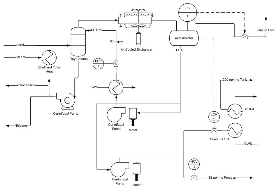
8. Piping and Instrumentation Diagram Examples
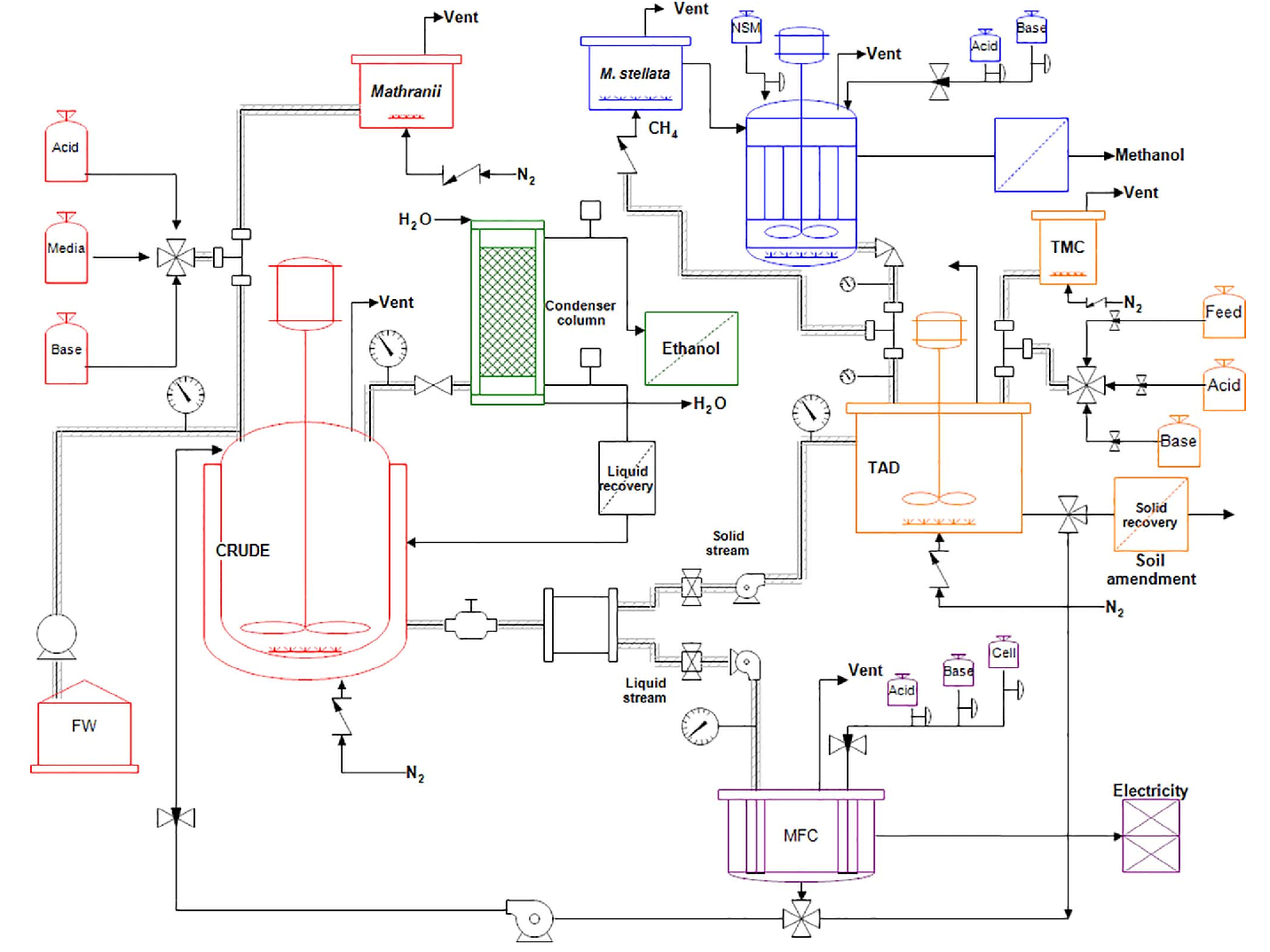
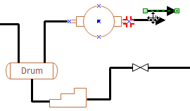
In the diagram below, a fluid flow system, demonstrated is the mechanical and model entities put in one place. It shows the relationship between the processes. The start is the Feed process and the arrows represent the subsequent step/stage of the chemical process. The end is the arrow marked 38gpm to Process. It is a simple diagram, as shown below. Find more P&ID examples.
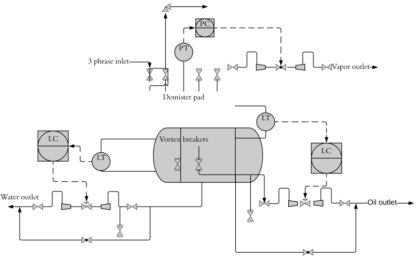
Below is a drawing of separator vessels in three phases. The components are commonly used to separate various fluids that flow from oil wells in the oil and gas industry. From the diagram, you can see the 3-phase inlet that branches to vapor outlet, water outlet, and oil outlet. In between are the separation processes to get the water, vapor, and oil extracted.
9. How to create a P&ID Effortlessly with Edraw?
Now that you know what a piping and instrumentation diagram is, how and when to use, its fundamental symbols, shapes to consider and illustrations, it is time we showed you how to make one using EdrawMax Online.
Scan Now


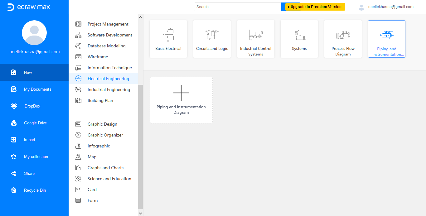
Step 1: Once you sign up, go to the File menu. Then, tap on New, Engineering, and double-click on Process and Instrumentation template. This will open a fresh drawing page.
Step 2: Now, go to the Library tab on the left side of the interface. From Equipment, drag equipment shape onto the drawing page.
Step 3: Next, use the pipelines to join the equipment. To create a connection point, use the Connection Point Tool under the Home tab, to set the pipeline style, go to the Home tab, and tap on the Line button.
Step 4: You can add valves and instruments in a similar manner.
Step 5: To rotate a shape, use the rotation icon when selected.
Step 6: Change the position of a shape, by dragging it to the required position.
Step 7: Lastly, add data to a component, double-click on it. When it's done, you can: print the diagram from the Print options in the File menu or export the diagram in several formats from the Export and Send for Export options on the File menu.
10. P&ID Diagram FAQ
How to read P&ID drawings?
P&ID drawing is a schematic representation of instrumentations, control systems, and pipelines used in any process development plant. It uses symbols to represent process equipment such as sensors and controllers. Every symbol contains letters and a number. The first letter represents the parameter like temperature, and the second letter represents the control device and its number in the system. Learn more how to read p&id drawing.
What to consider when choosing a P&ID software?
Making a P&ID diagram is a complicated process, and you need software that makes things easier for you. Various software allows you to make detailed diagrams, but you have to look for the one with the most significant number of detailed symbols and icons that you can use and lets you import or draw symbols like EdrawMax Online.
What is the function of the piping and instrumentation diagram?
The function of P&ID is to depict the entire engineering process related to the development and installation of a process plant. It indicates the relationship between equipment, piping, the flow of control and control devices with the help of a detailed diagram. It functions as the base of any process plant and is also used for modification and maintenance after installing the plant.