Logic Gate Symbols and Truth Tables
1. What Are Logic Gate Symbols
Logic Gate is an idealized model of a physical electronic device that implements a Boolean Function. Logic Gates are also called the building blocks of the digital Electronic Circuit which are very usable nowadays. Logic Circuits include devices such as computer memory, multiplexers, and arithmetic logic units.
Logic Gate Symbols are usable nowadays as they are called the building blocks of a digital Electronic Circuit so they are used in each and every digital circuit. They are usually dependent on Boolean Function. There is much other information about these Logic Gates which are going seen in this article so read it carefully.
Logic Gate Symbols are the graphical representation of the logic gates which are usually used to make digital circuits. Some symbols of logic gates are given below:
2. Logic Gates Symbols Explained
2.1 Standard Logic Gates Symbols
Logic Gates Symbols are usually used for the graphical notation of the logic gates. Due to these, we can easily recognize the Gate. As in schools we only learn about one type of Gate symbol i.e. Traditional Symbols. But there are two types of symbols which are listed below;
There are two types of Logic Gates Symbols
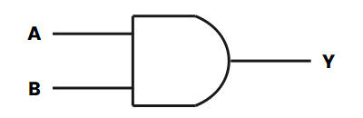
Traditional Symbols
These are normally used symbols and have distinctive diagrams which help us to easily recognize them. Usually, we use this type of symbol very much. As in Schools, we study only these traditional Symbols.
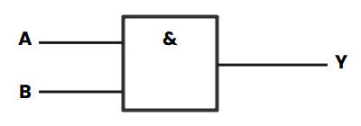
IECS Symbols
Here IECS means International Electro technical Commission Symbols. They are rectangular in shape and have a symbol inside them to show the gate functions. These types of symbols are very hard to understand but they are used for higher purposes.
2.2 Below Are the All 5 Numbers of Logic Gate Symbols and Truth Tables
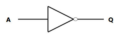
NOT Gate
It is a type of gate that has only one input as well as one output. This Gate is also called an inverter. When the input is 1 the output is 0 and when the input is 0 then the output is 1 so that's why it is called an inverter. OUTPUT=NOT A
AND Gate
It is the type of gate that has two or more two inputs as well as one output. Its output is ON when both inputs are true. OUTPUT= A and B
OR Gate
It is the type of which can have two or more than two Inputs but have single Output. Its output is ON when at least when one input is ON. OUTPUT= A OR B
NAND Gate
This gate is made up of the combination of two other gates that are NOT and AND Gate. Here all set is like AND Gate but the output is inverted by NOT Gate. Here the output is OFF when both the INPUT is ON. OUTPUT=NOT (A and B)
NOR Gate
This gate is also made from the combination of the other two gates that are NOT and OR Gate. Here in this Gate, the OUTPUT is ON when both inputs are OFF. OUTPUT= NOT (A OR B)
Digital Logic Gate Truth Table Summary
The truth table is used to show the functions of logic gates. Every possible combination of the input state shows its output state. The input and output are in the form of 1 and 0 which means ON and OFF State.
The following table shows the input and output summary of all the Logic Gates which are explained above:
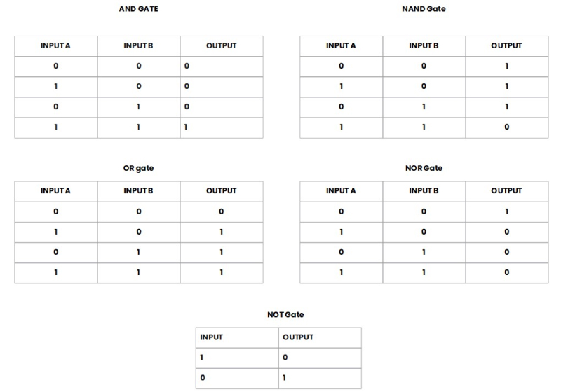
Source: EdrawMax Community
NAND Gate Equivalents
NAND Gate is made up of the combination of two other gates that are NOT and AND Gate. Here all set is like AND Gate but the output is inverted by NOT Gate. Here the output is OFF when both the INPUT is ON. OUTPUT=NOT (A and B)
This gate is equivalent to an inverted input OR Gate. From this gate, we can make every other gate like NOT Gate, AND Gate, OR Gate, and all rest of the gates. Following Diagrams shows the combination of NAND Gate which make other gates:
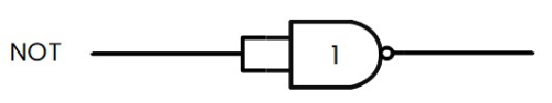
NOT Gate made from single NAND Gate
We can easily make NOT Gate by using NAND Gate only we have to joint the input of NAND Gate together then it behaves like NOT Gate. So we can say that NOT Gate is made from a single NAND Gate easily
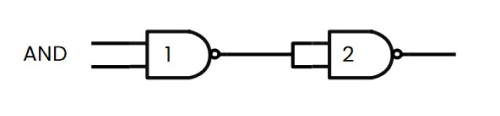
AND Gate made from the combination of two NAND Gates
We can also make AND Gate Using this NAND Gate but here we have to use two of them as shown in the diagram. So we can say that AND Gate is made from a joint of two NAND Gate easily.
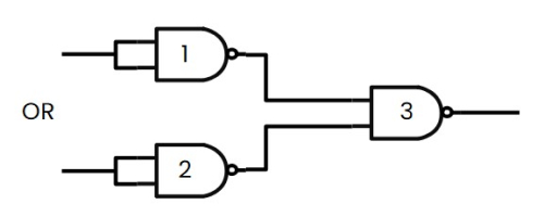
OR Gate made from the combination of three NAND Gates
We can also make OR Gate Using this NAND Gate but here we have to use three of them as shown in the diagram. So we can say that OR Gate is made from three NAND Gate easily.
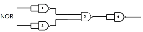
NOR Gate made from the combination of four NAND Gates
We can also make NOR Gate Using this NAND Gate but here we have to use four of them as shown in the diagram. So we can say that NOR gate is made from four NAND Gate easily.
3. Tips for Using Logic Gate Symbols
If you want to draw a circuit and you need Symbols for that then you have to use EdrawMax Online to find out Symbols of Logic Gates and other Electronic components.
3.1 Use a Professional Circuit Diagram Tool
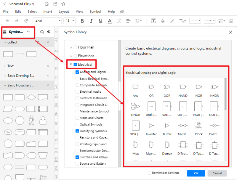
You can quickly find out the Symbols of Logic Gates in EdrawMax Online by just simply clicking on the Symbol Library and choosing your desired symbol there. You can get almost all the Symbols that we need to draw the circuit diagram such as Resistance, Capacitor, Inductor, Logic Gate, etc. You can also follow the following image to get more information about this:
3.2 Create Symbols by Yourself
If you didn't get your desired symbol in this EdrawMax Online Symbol Library then you can also import the symbol in Library.
Suppose you have to draw the circuit diagram and you need a symbol that is not there then you can also import the file of that symbol. You can also create the Symbols in EdrawMax Online easily. From the following image, you can understand better.

You can also learn more from this video. YouTube.
4. More Questions about Logic Gate Symbols
We have provided all the information about Logic Gate and Its Symbols. But I know you have many quarries about that, we have listed some questions might they help you.
Why do we call them Gates?
They are the device that implements Boolean Function which means it makes logic operations on one or Zero in inputs and gives a bit in output. They are also called the building blocks of a digital circuit.
Where do we use Logic Gates?
As we already discussed that Logic Gates are the building blocks of a digital system and Circuits. So we use Logic Gates in making digital circuits such as microcontrollers, microprocessors, electrical and electronics projects, and embedded types applications.
How many inputs signals can a Gate have?
As you know that there are six types of gate NOT, OR, AND, NAND, OR Gate. NOT Gate has only one input with two possibilities i.e. 1 and 0 but in other gates like AND, OR, NOR, and NAND we have two inputs with four pairs of the possibility of 1 and 0.
5. Conclusion
So from the above information, you have got all the information about Logic Gates and its Symbols. We have also explained the functions of a Logic Gate and its Truth Table.
If you want to use Logic Gate Symbols, then EdrawMax Online is the best software through which you can quickly get these Symbols. Find more circuit diagram examples in the templates community.