How to Design a Digital Logic
1. Introduction
Before you learn to design a digital logic, it is better to understand its definition and uses in engineering. A logic gate is mainly used to produce input and output operations in computer and electrical engineering. We use it to develop hardware electronic devices and measure the frequency of waves or pulses. Microchips and circuit boards are also designed from digital logic systems. We also use logic gates in education to perform binary operations.

2. How to Design a Digital Logic
Digital logic design is fundamental because electronic systems, electrical engineering, and computer engineering work on their basis. Digital logic helps create complex circuits based on various functions to execute specific operations. Logic gates are the building block of any digital circuit, and we use them to transfer digital messages and simplify both input and output. Digital logic is also used in industrial plants to define safety parameters and detect unusual actions in the system. Follow the five steps down here to easily design a digital logic for any project or educational purpose.
Step 1: Understand the given specifications
Before designing a digital logic, your first job is to understand the human-readable specifications. It will help you know why you need to create the digital logic and what output the system requires. You could only move towards the next step after analyzing the given specifications. If you want to develop a new digital logic, you have to write the specifications yourself.
Step 2: Find the number of inputs and outputs
It is essential to find the number of inputs and outputs to design a digital logic. You can do this step by thinking of the logic operation you want to perform with the digital circuit. It is similar to determining components of a diagram. Take a simple digital circuit that adds two inputs and gives one output as an example. From the given specification, you can easily consider that the number of inputs is two, and there is only one output.
Step 3: Create a truth table
After learning the number of inputs, you can create the truth table for your digital logic circuit. A truth table tells you the outputs for your logic design's given the number of inputs. The columns of the truth table represent the outputs and inputs, while the rows give you all the possible values of input in the circuit. Even if your digital logic is easy to understand, you need to create a truth table to move to the next step.
Step 4: Draw a Karnaugh map
After creating a truth table, you must draw a Karnaugh map or K map. We do this step to simplify the Boolean function for each output, and it helps you minimize expressions depending on their number of variables. It is easy to streamline expressions with 2 to 4 variables easily, but it gets harder from this point. You can minimize functions with 5 to 6 variables using K map by putting in some effort.
Step 5: Draw the circuit diagram
The final step to design a digital logic is making a circuit diagram. Make sure there are no changes between the inputs and outputs of your diagram based on the truth table you created earlier. A circuit diagram uses logic gates to perform operations using simple values and return clear output. You can also describe your digital logic by drawing a wiring diagram. Use logic gate symbols and icons for this step.
If the video doesn't play, please visit it at YouTube.
3. How to Design a Digital Logic with EdrawMax Online
It would help if you had various logic symbols and icons to design a digital logic. Using EdrawMax Online to create your digital logic design makes your job effortless and saves time. You don't even need to design the digital logic from scratch because EdrawMax gives you a comprehensive template library. It also comes with various customization tools to help you edit your diagram. Follow the given steps to create a digital logic using EdrawMax Online.
Open EdrawMax Online and sign up to create an account. If you already have an account, then log in. All you have to do is enter your username and password.
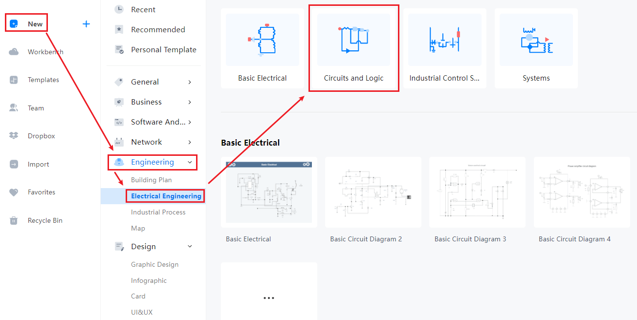
After you sign in, navigate to Engineering>Electrical Engineering>Circuits and Logic. After that, you can click on it to get a blank canvas. You can start creating the diagram, and you can look for symbols in the symbol library to the left side of the canvas.
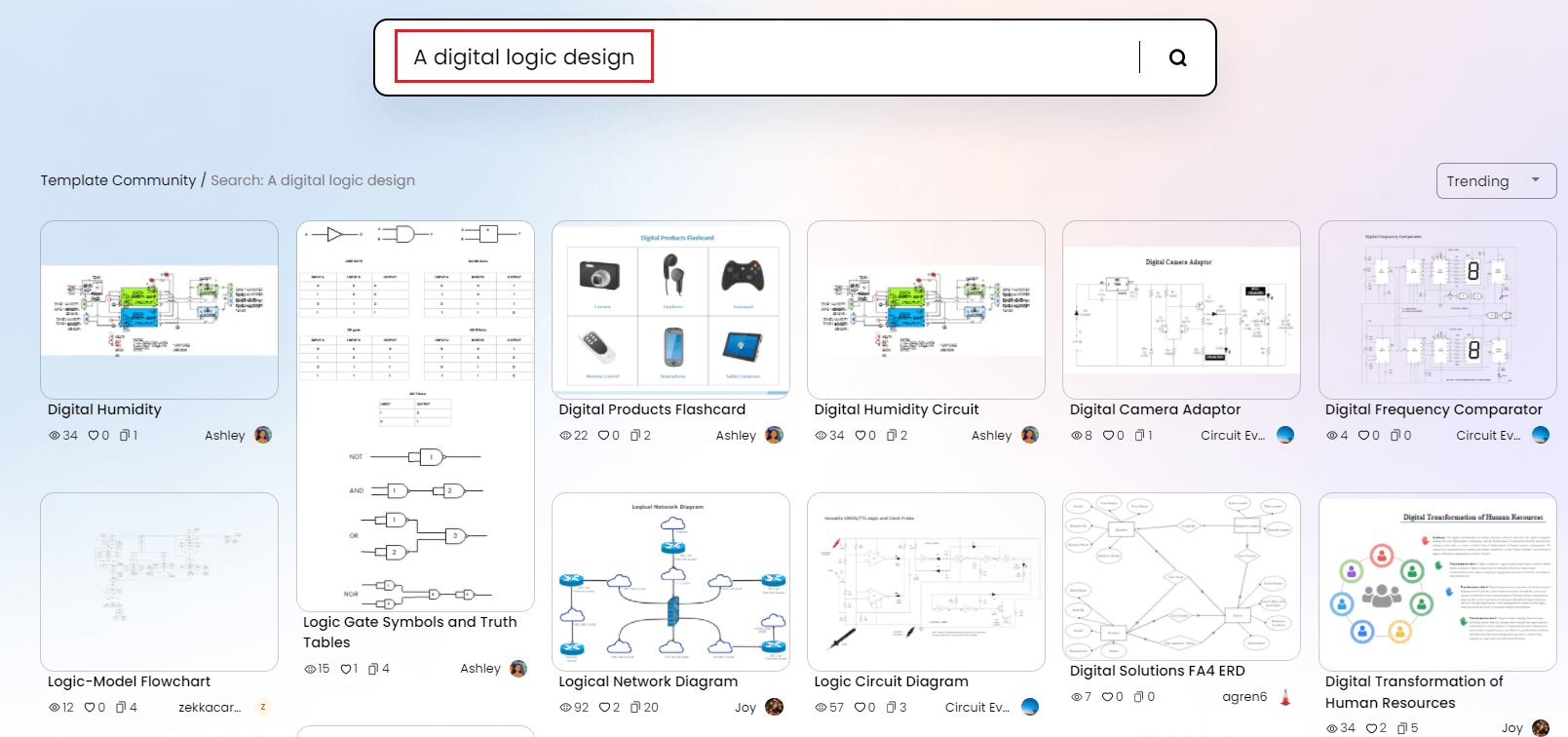
You can also look for templates in the EdrawMax Online template library. All you have to do is either go to templates or click the search bar. Type the diagram's name and get a comprehensive list of templates professionally made for you. You can easily make changes to these templates according to your requirements. Find more templates in Templates Community.
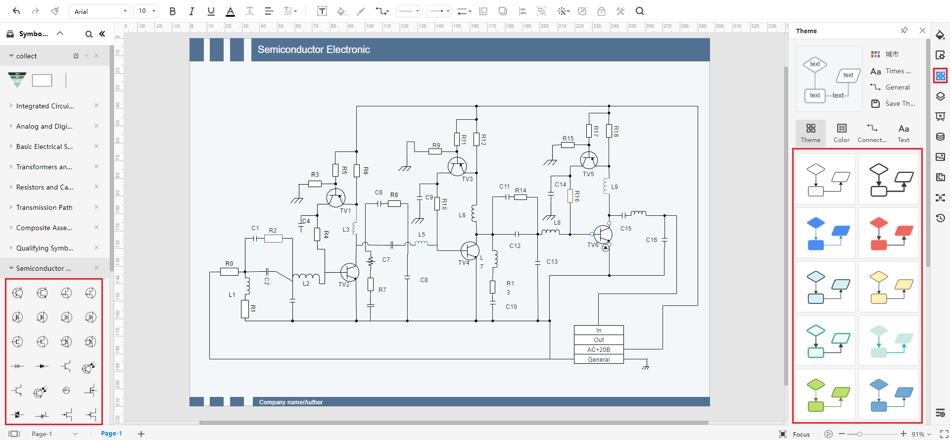
You can customize your logic design by using symbols from the library. You have to click and drag the symbols you need and add them to your diagram. You can also add text and change font styles and text colors. You can add shapes, and there is a toolbar at the top of the canvas with various customization options.
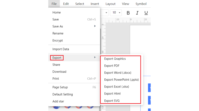
You can save your drawing in all popular formats using EdrawMax Online. You have to go to files and click the save or export options. Please select the format you require, such as docs for a text file or jpeg to export it as an image.
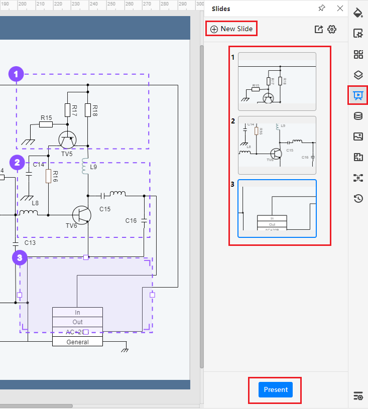
You can create presentations on EdrawMax Online for your project. You can add slides to explain your diagram, and you can style every slide differently to make it more creative.
4. Expert Tips for Making a Digital Logic
Tip 1: Understand logic gates
To create a perfect digital logic design, you need to understand the functions and uses of logic gates in a digital circuit. Logic gates are essential for any digital logic. The Boolean operations and other complex processes are quickly completed using logic gates. You can use combinations of logic gates to solve or represent complex functions. Before designing a digital logic, make sure you know the basic types and symbols of logic gates.
Tip 2: When to draw a K-map
A pamphlet usually contains pictures and text content, and you have to make sure that the readability is perfect. The purpose of having a brochure is to attract the audience to whatever you are advertising, and if they get bored reading the text or it is hard to read and get a general idea, they will not move past the front page. Use bullets to focus on the main points for an audience who doesn't have time to read the whole thing.
Tip 3: Review
After completing your digital logic design, you should review it from top to bottom before applying it to a digital circuit. Check your truth table and consider the number of inputs and outputs. Go over the human-readable specifications once more and ensure that your digital design defines the required logic. If you can find any mistake, send it to your trusted colleagues to get it reviewed once more.
5. Key Takeaways
A digital logic design is a system that uses simple values to produce functions, perform operations and define the input and output of any digital circuit. It is mostly used in electrical and computer engineering to develop the basic circuitry for electronic devices, microprocessors, and hardware. You can easily design a digital logic after in a few steps. Start with finding the input and output and create a truth table. Draw a Karnaugh map and create a logic diagram based on it. Find more circuit diagram templates.
EdrawMax Online is one of the best diagramming software with an easy-to-use interface that helps you draw 300 types of charts and diagrams. You can use it to design digital logic without quickly wasting your time and effort. It comes with a template library that you can use for your diagram, or you can use its symbols and icons to create one from scratch.