What is Process Flow Diagram (PFD)
Create a Process Flow Diagram Online Free Free Download Free Download Free Download Free DownloadA process flow diagram is a graphical tool most commonly used by business process management professionals (BPM) and chemical engineers. PFD helps to understand the process, provide quality control, and increase efficiency. It is used to get a top-down understanding of how different types of equipment and chemicals work in the industrial plant. It maps various tasks and shows what repeatable tasks you may need to perform to achieve a specific goal.

Now, let’s discuss the brief definition of the process flow diagram and how it differs from P&ID.
What is a Process Flow Diagram?
Brief Description of PFD
This diagram dates back to the 1920s, and in 1921 Frank Gilbreth initiated the “flow process chart.” Since then, many industrial engineers, businesses, and manufacturers use this chart.
It is a type of flow chart that is utilized in chemical engineering and process engineering. A process flow diagram illustrates the equipment and the flow of chemicals included in the process. The PFD only shows major equipment such as pumps, vessels, columns, heaters, turbines, etc. at an industrial plant.
However, it does not show minor details or components like designations, flow instruments, pipe properties, and piping details (drain lines, control loops, bypass lines).
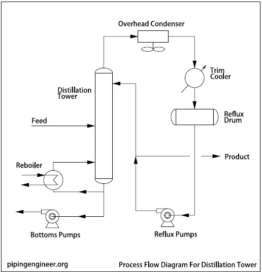
Image Source: pipingengineer.org
Differences between PFD and P&ID
A PFD is a simplified version of Piping and instrumentation diagrams (P&ID). In contrast, P&IDs provide more details, which includes instrumentation details (flow instruments, temperature, pressure, pressure safety valves, meters and control valves), pipe routing conditions (minimum distance, slope, free flow, etc.), and piping details (size, specifications, service, insulation, rating).
Furthermore, to understand P&IDs, you will need a legend sheet which is usually given by a P&ID developer. The legend sheet has all the information like symbols, terminology, etc., which is also called “flowsheets.”
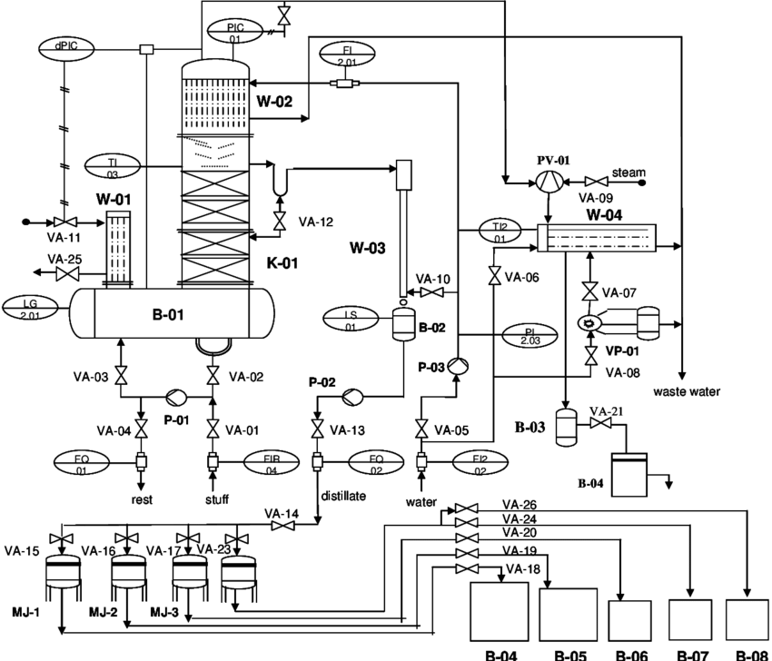
Image Source: researchgate.net
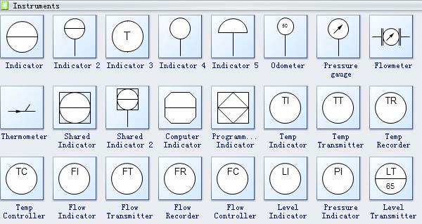
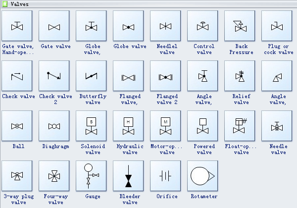
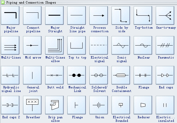
Symbol Library for Process Flow Diagram
Here is a list of elements that a typical process flow diagram includes for process and chemical engineering.
- Main equipment - Includes ID numbers and names.
- Process-critical valves
- Control valves
- Recirculation system
- Major bypass system
- Process of piping
- Flow direction process
- Fluids composition
- Process steam names
- Operational data - It includes temperature, pressure, density, mass-energy balance, and mass flow rate.
- Connections with various systems
Examples: compressors, agitators, centrifuges, apparatus elements, drivers, feeders, engines, mixers, pumps, separators, valves, coolers, mixers, and boilers.
How to Plan and Create a Process Flow Diagram
To plan and create a PFD, you have to follow these steps mentioned below.
● First, you need to define your process’s scope. Mention what you want to study and what you will obtain from it.
● Next, decide what kind of details you will need for your purpose. Various editions of PFDs are available for intricate processes that you can use or draw to communicate with people.
● It is essential to study relationships, activities, and equipment with the help of interviews and observations. If you are making a new process model, try to learn and understand the available data. Furthermore, it is crucial to study the standards of whatever you are trying to produce in the process.
● Now draw a rough sketch and confirm it with your team members. It is vital to make a draft and seek approval from the people involved in this process because it will help you to make necessary changes, you can add stuff, or delete any errors.
● Finally, your diagram is ready to be used for its intended purpose. Your goal might be to provide quality assurance, documentation, or improvement.
Use EdrawMax Online to Create a PFD
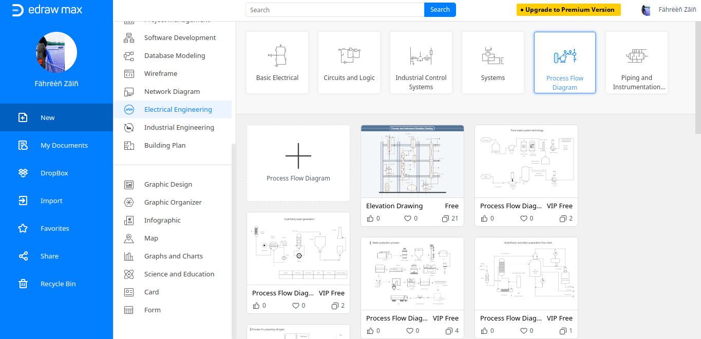
● To create a PFD online, open EdrawMax Online(https://www.edrawmax.com/online/) on your laptop or PC.
● Select Electrical Engineering > Process Flow Diagram and click the + to enable a blank page. Or, you can click on one of template thumbnails to open a pre-made template.
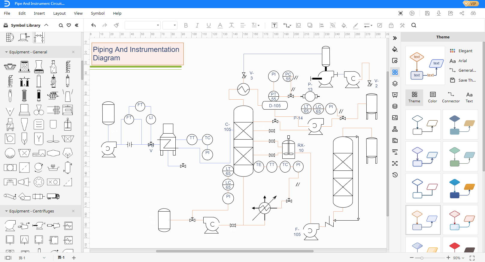
● On your left is the symbol library. All the equipment, valves, pipes are present here. Drag and drop the symbols that you need to create your PFD. Style the diagrams with formatting tools. Here is an example:
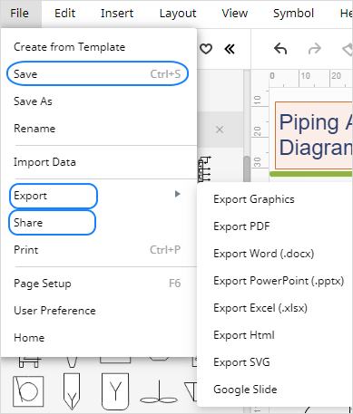
● Once you are finished and happy with your work, save, export or share your work.
Free Process Flow Diagram Templates
A free template can entice anyone to make a process flow diagram swiftly. You can take help from these templates by either modifying a little, starting from scratch or using it as it is. Here are some templates of process flow diagrams:
Cooling Process Flow Diagram - Create a simple cooling process flow diagram to show how the whole cooling process works. The template uses a variety of symbols, and it is perfectly colored.
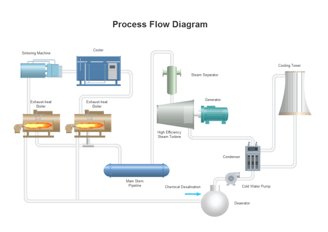
Click here if you want to download and use cooling PFD right now.
Petroleum Refinery Process Flow Diagram - Create by using the petroleum refinery process flow diagram template from SmartDraw. This template is ideal for engineers. It is detailed and contains shapes that are appropriately labeled.
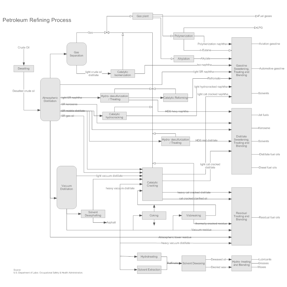
Click here if you want to download and use this template for describing the petroleum refining process.
De-oxidization Process Flow Design - Do you want to describe the de-oxidation process in an effortless manner? Then, use this template as it contains symbols, and it is also correctly labeled and colored.
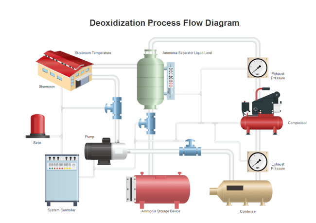
Click here if you want to download this template to create a de-oxidization process flow diagram.
Solar Heating Process Flow Diagram - Make use of a solar heating process flow diagram from the SmartDraw. This template is labeled and contains instrument and valve symbols with piping and connecting shapes.
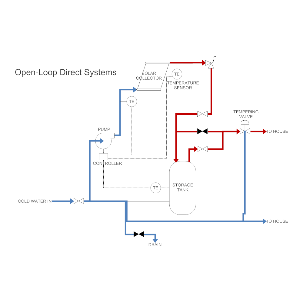
Click here if you want to download and use this template straight away.
Active Lime Production Process Flow Diagram - It is another easy-to-use template by EdrawMax for engineers to understand the process of active lime production. The drawing is perfectly colored and aligned.
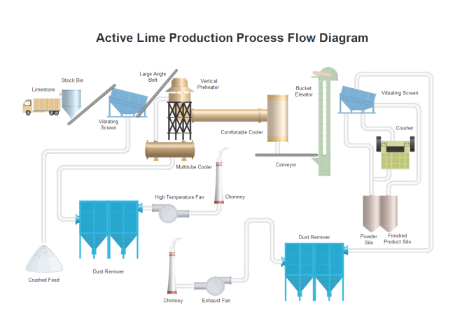
Click here to download and use this template right away!
Summary & Suggestion
The PFD is a fundamental and noncomplex version of P&ID. It is a chemical and process engineering drawings that are useful because they convey accurate information required during the different stages of engineering design, procurement, bidding, operating, commissioning, and constructing phase of the process.
The process flow design uses major equipment, whereas the P&ID shows both major and minor details, which is more sophisticated.
Moreover, creating a PFD is easy; you just have to use the right software, utilize the desired free template, and edit according to your needs.


